

-
About Us
-
-
-
Contact Us

Shaft Cross-Section Shape and Size Design — Black Diamond Report
Design of Shaft Cross-Section Shape and Size
1. Classification of Shaft Cross-Section Shapes and Selection Criteria
(1) Comparison of Mainstream Cross-Section Shape Characteristics
In mining operations, the shaft serves as a critical passage connecting the surface and underground. The choice of its cross-sectional shape directly affects the safety, economy, and construction efficiency of the project. Shaft cross-sections are diverse, mainly including circular, rectangular, and elliptical shapes. Among them, the circular cross-section, due to its unique advantages, is the most commonly used form.
The circular cross-section excels in mechanical performance and construction convenience. Its symmetrical structure can evenly distribute ground pressure and effectively withstand large surrounding rock loads, especially suitable for medium to large mines under deep mining and complex geological conditions. In deep mining, as ground pressure increases, the stability advantage of the circular cross-section becomes more apparent, providing reliable support for the shaft and ensuring safe mine production. Additionally, the circular cross-section facilitates the use of formwork support and mechanized construction, greatly improving construction efficiency and reducing costs. Moreover, its maintenance costs are relatively low, offering good long-term economic benefits.
The advantage of the rectangular cross-section lies in its simple construction and high utilization of cross-sectional area, making full use of space. However, its bearing capacity is relatively weak and is only suitable for small mines with low ground pressure and short service life (not exceeding 15 years). In such mines, the rectangular cross-section can meet basic usage requirements at a lower cost, thus having certain application value. Polygonal cross-sections (such as hexagonal) are occasionally used under specific geological conditions, but due to stress concentration at the corners requiring additional reinforcement, their applicability is limited.
Elliptical cross-sections are usually used in the reconstruction or expansion of old shafts. They cleverly utilize the original rectangular shaft space by reasonably adjusting the ratio of the major to minor axes to optimize the stress structure. In engineering scenarios where the cross-section needs to be enlarged in narrow sites or to pass through complex geological layers, the elliptical cross-section shows unique adaptability and can solve engineering difficulties under special conditions.
(2) Key Factors Influencing Selection
- 1. Geological Conditions Geological conditions are an important basis for selecting the shaft cross-sectional shape. Under complex geological conditions such as high ground pressure, soft rock, or fractured rock layers, the circular cross-section is the preferred solution due to its excellent compressive resistance and stability. In stable rock layers with relatively low ground pressure, the rectangular cross-section can reduce construction costs and improve economic benefits while meeting engineering requirements.
- 2. Service Life Service life is also a key factor to consider when selecting the shape. For long-term operating mines, the durability and stability of the circular cross-section make it an ideal choice, ensuring safe and reliable shaft operation over a long period. For short-term small projects, the rectangular cross-section has advantages due to its simple construction and low cost.
- 3. Functional Requirements Different functional requirements also impose different demands on the shaft cross-sectional shape. Main shafts and auxiliary shafts with large hoisting volumes need to ensure safety and stability, which the circular cross-section can better satisfy. Ventilation shafts, drainage shafts, and other auxiliary shafts can flexibly choose rectangular or circular cross-sections based on specific ground pressure conditions to balance function and cost.
2. Method for Determining Shaft Cross-Section Dimensions
(1) Steps for Designing Net Cross-Section Dimensions
- 1. Basic Parameter Determination Determining the shaft cross-section dimensions is a rigorous and critical process. The determination of basic parameters directly affects the subsequent use efficiency and safety of the shaft. Based on the mine's production capacity and hoisting method (cage / skip), select the specifications and quantity of hoisting containers, clarify the shaft layout form (single container / double container + ladder compartment / cable compartment). Choose the cage guide (rigid / wire rope), cage guide beam model, and calculate safety clearances (minimum distances between hoisting containers and shaft walls or equipment must comply with standards).
- 2. Geometric Dimension Calculation The calculation of geometric dimensions is the core step in determining the shaft cross-section size, mainly achieved through graphical and analytical methods.
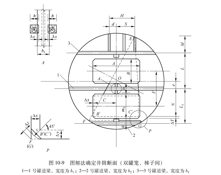
- • Graphical Method Draw the shaft component layout diagram at a scale of 1:20 or 1:50, determine key coordinate points of the hoisting compartment and ladder compartment (such as the centerline spacing of cage guide beams and ladder compartment boundaries), solve the approximate diameter using the circumscribed circle method, and upgrade the modulus by 0.5m (for net diameters ≤6.5m) or 0.2m (>6.5m).
- • Analytical Method Establish geometric equations to simultaneously solve for shaft radius and center offset, applicable to complex layouts such as double cage shafts. Verify cage corner shrinkage dimensions and safety clearances (formulas as shown).
- 1. Ventilation Check Ventilation check is an important step to ensure normal shaft operation. Calculate the air velocity, where the effective ventilation cross-sectional area (subtracting the area occupied by the ladder compartment if present) and the allowable maximum air velocity must comply with standards (e.g., for personnel hoisting shafts). Through ventilation checks, the air quality and ventilation effectiveness inside the shaft can be guaranteed, providing safety assurance for mine production.
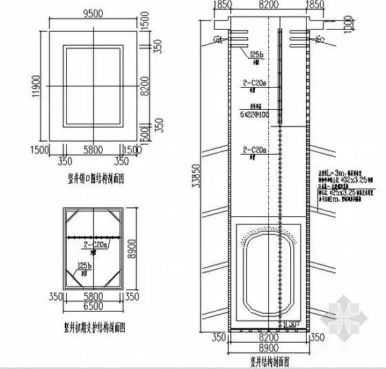
(2) Typical Shaft Cross-Section Design Example
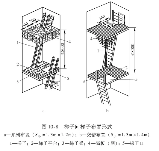
- 1. Rigid Cage Guide Cage Shaft Taking the double cage + ladder compartment layout as an example, determine the centerline spacing of cage guide beams (), ladder compartment dimensions (length , short side spacing ), and adjust the shaft diameter according to safety clearance requirements. Finally, verify ventilation efficiency through air velocity calculations. In actual engineering, a mine shaft adopted this layout form. Through precise calculation and design, all performance indicators of the shaft met production needs, providing strong support for efficient mining.
- 2. Wire Rope Cage Guide Shaft More than four hoist ropes must be symmetrically arranged to reduce container sway and increase the safety clearance (10%-15% more than rigid hoist ropes). Deep wells require anti-collision steel wire ropes (spacing is 3/5 to 4/5 of the container length), with single-side or diagonal arrangements to optimize stress. In a certain deep well mining project, due to the deep shaft, steel wire rope hoist shaft was used, and the hoist ropes and anti-collision steel wire ropes were reasonably arranged, effectively reducing container sway and collision risk, improving the stability of the hoisting system.
3. Key Technologies in Wellbore Structure Design
(1) Determination of Wellbore Wall Thickness
- 1. Influencing Factors The determination of wellbore wall thickness is a key step in wellbore structure design, influenced by multiple factors. Ground pressure is the primary factor, playing a decisive role in wall thickness. When shaft ground pressure is less than 0.1 MPa, the minimum structural thickness can be used, ranging from 0.2 to 0.3 m, which meets basic structural stability requirements. In some geologically stable areas with low ground pressure, this thickness ensures wellbore safety. When shaft ground pressure is between 0.1 and 0.15 MPa, thickness h can be estimated by an empirical formula, where r is the inner radius of the shaft and H is the total depth. This empirical formula, based on extensive engineering data, accurately estimates wall thickness within this pressure range. When ground pressure exceeds 0.15 MPa, the force on the wall increases significantly, requiring precise calculation using thick-walled cylinder theory, i.e., Lamé's formula, to ensure the wall can withstand the strong ground pressure.
The choice of support materials also significantly affects wall thickness. Concrete wellbore walls are common, typically using C20 concrete. Thickness increases with shaft diameter; for a net diameter of 3.0 to 4.0 m, concrete wall thickness is 250 mm; when diameter increases to 7.5 to 8.0 m, thickness increases to 500 mm. This is because larger diameters bear greater pressure, requiring thicker walls for stability. Shotcrete walls have different thickness requirements depending on geological conditions. In stable rock formations, thickness can be 50 to 100 mm, sufficient for support. In slightly poorer geology with developed joints but low ground pressure and relatively stable rock, thickness should increase to 100 to 150 mm to enhance support. For poor geology with fractured rock, shotcrete alone is insufficient; combined shotcrete, anchoring, and mesh support with thickness of 100 to 150 mm is used to improve stability through multiple support methods.
- 1. Stability Verification To ensure long-term stability of the wellbore in complex underground environments, strict verification of the lateral stability of the wellbore ring is required. The lateral slenderness ratio (for concrete walls) or (for reinforced concrete walls) is used for preliminary assessment, where L is the lateral equivalent length of the wellbore ring and t is the wall thickness. This indicator preliminarily judges whether the wall stability meets requirements. Combined with Lamé's formula to check compressive strength, considering factors such as elastic modulus under compression, calculation height of the wellbore ring, distance from the ring's centroid to shaft center, lateral pressure per unit area, and Poisson's ratio of the material, a comprehensive evaluation of lateral stability under uniform load is performed to ensure the wall can withstand various pressures and guarantee mine safety. In practice, a mine adjusted wall thickness based on strict stability verification, preventing accidents caused by wall instability and ensuring long-term stable operation.
(2) Design of Wellbore Wall Seat
- 1. Forms and Applications The forms of wellbore wall seats mainly include single-cone and double-cone wall seats, each applied under different geological conditions and engineering needs. Single-cone wall seats suit hard rock formations, with simple structure and smaller bearing capacity. In hard rock, due to inherent stability, single-cone seats meet support requirements. Their height is generally 1 to 1.5 m, width between 0.4 and 1.2 m, and cone angle about 40°, parameters derived from long-term engineering practice ensuring stability and bearing capacity in hard rock.
Double-cone wall seats are mainly used in soft strata or high-load areas. Their unique double-cone surface structure effectively disperses pressure and increases bearing capacity. In soft strata with high ground pressure and poor stability, double-cone seats better adapt to geological conditions, providing reliable support. In high-load areas, such as above the horsehead frame, where pressure is large, the bearing advantage of double-cone seats is fully utilized. The β angle of double-cone seats must be less than the static friction angle between the seat and surrounding rock (generally 20° to 30°) to prevent sliding inward under pressure, ensuring wall stability.
- 1. Structural Dimensions The structural dimensions of wellbore wall seats must follow strict standards to effectively enhance overall support capacity. Seat height should be no less than 2.5 times the wall thickness, and width no less than 1.5 times the wall thickness. These proportions ensure sufficient strength and stability under pressure. C20 to C30 concrete is used for casting, meeting bearing requirements. Structural reinforcement bars (non-load bearing) are configured; although they do not bear main loads, they improve concrete tensile strength and crack resistance, ensuring durability and stability.
Wellbore wall seats are usually set below the shaft collar, above the horsehead frame, or at thick surface soil layer boundaries. Below the shaft collar, seats support loads from the hoist and shaft equipment, providing a stable foundation. Above the horsehead frame, which connects the shaft to the bottom car station and bears large pressure, seats enhance wall strength to ensure safe use. At thick surface soil boundaries, seats effectively disperse soil pressure, preventing deformation or damage to the wall. Setting seats at these key locations significantly enhances overall wall support capacity, ensuring safe and stable shaft operation.
4. Engineering Applications and Optimization Suggestions
(1) Design Process Optimization
- 1. Geological Survey and Preliminary Planning At the initial stage of shaft design, early involvement in geological survey work is crucial. Through detailed investigation of surface hydrology and rock layer distribution, a more precise selection of the appropriate cross-sectional shape can be made. In a certain mining project, due to insufficient preliminary geological survey, the shaft encountered complex geological conditions during construction, forcing adjustments to the cross-sectional shape. This not only increased construction difficulty but also caused delays and cost overruns. If geological factors and surface hydrology are fully considered at the design stage to select a suitable cross-sectional shape, later reconstruction due to geological issues can be avoided, thereby reducing costs and improving engineering efficiency.
- 2. Application of Digital Technology Using BIM technology for 3D modeling has brought revolutionary changes to shaft cross-section design. Through BIM, visual verification of the gap between the hoisting container and shaft wall, as well as ladder compartment layout, can be conducted, greatly improving the accuracy of diagrammatic methods. In a large mining shaft project, BIM technology was used in design to not only detect the issue of insufficient gap between the hoisting container and shaft wall in advance but also optimize the ladder compartment layout, ensuring smooth construction while enhancing shaft safety and operational efficiency.
(2) New Materials and Processes
- 1. Application of New Support Materials In shaft construction, promoting the use of new materials such as fiber-reinforced concrete and prefabricated modular shaft walls offers significant advantages. Fiber-reinforced concrete effectively enhances the crack resistance of shaft walls, especially suitable for water-permeable strata. In a shaft project within a water-permeable stratum, using fiber-reinforced concrete as the support material successfully resolved cracking issues caused by water seepage, improving the durability and stability of the shaft walls. Prefabricated modular shaft walls greatly accelerate construction speed, reduce on-site construction time, and lower costs. Their factory production also ensures stable product quality, providing reliable assurance for shaft construction.
- 2. Application of Intelligent Tensioning Systems For wire rope cage shaft systems, adopting a hydraulic tension automatic adjustment system is an effective optimization measure. This system can automatically adjust the wire rope tension based on the operating status of the hoisting container, reducing the extra cross-sectional size requirements caused by container sway. In a wire rope cage shaft project, after installing the hydraulic tension automatic adjustment system, container sway was significantly reduced, safety clearance was effectively controlled, allowing for a smaller shaft cross-section, reducing construction costs, and improving the safety and stability of the hoisting system.
Shaft cross-section design is a complex and systematic project that requires comprehensive consideration of geological conditions, functional requirements, and economic factors.

Previous Page
