-
About Us
-
-
-
Contact Us
Shaft Well Drainage and Water Control—Heijin Gang Reports
I. Introduction
In mining engineering, the shaft serves as a critical link between the surface and underground, making drainage and water-control operations during construction and operation absolutely essential. The presence of groundwater is one of the primary challenges faced during shaft construction, with its adverse effects being both widespread and significant—severely threatening the project’s safety, quality, schedule, and cost management.
When shaft construction encounters groundwater, working conditions can deteriorate dramatically. Underground water inflows make the working face of the shaft slippery, significantly increasing the risk of accidents such as slips, trips, and falls among construction workers. At the same time, these water flows can disrupt the normal operation of construction equipment, shortening its lifespan and reducing overall efficiency. During the excavation and lining process of the shaft, substantial water inflows can compromise the stability of the surrounding rock mass, heightening the likelihood of shaft wall collapses and ultimately compromising the quality of the shaft walls. Moreover, if the rising water carries sediment or other impurities, it may even clog the shaft’s drainage pipes and grouting holes, creating additional challenges for subsequent water-control measures.
The impact of groundwater on project progress cannot be overlooked. Water inflows can make excavation and support work significantly more challenging and time-consuming, often requiring additional drainage measures and advanced support techniques—processes that undeniably increase the time and cost of construction. In some cases, to ensure construction safety, it becomes necessary to temporarily halt operations while waiting for the water-inflow issue to be resolved. This not only delays the project schedule but could even affect the overall construction timeline of the entire mine.
From an economic perspective, treating groundwater requires significant financial investment. Not only must drainage equipment and grouting materials—and other supplies—be purchased, but additional labor costs for construction workers and expenses for equipment maintenance and upkeep must also be covered. Moreover, if water inflow issues compromise the quality of the project, rework and repairs will become necessary, further driving up overall project costs.
More seriously, groundwater can trigger well-flooding accidents. Once a well is flooded, it not only leads to equipment damage and casualties but also has long-term adverse effects on mine production, potentially even forcing the mine to shut down entirely. Therefore, effectively controlling and managing groundwater in the shafts of vertical shafts is a critical step in ensuring the smooth operation of mining projects.
To achieve this goal, thorough geological surveys must be conducted prior to construction, ensuring a detailed understanding of the properties, structures, and hydrological conditions of the rock layers through which the well shaft will pass. This includes information such as the number of aquifers, water pressure, groundwater discharge rates, permeability coefficients, burial conditions, as well as details about fault fractures, karst caves, mined-out areas, and their connections to surface water bodies. Such data will provide crucial insights for selecting an appropriate water-control strategy.
In practical operations, drainage and water control work can be divided into two stages. First, prior to well excavation, preliminary treatment is carried out by blocking water-inflow channels and reducing or isolating the sources of water entering the well—such as implementing ground pre-grouting, external wellpoint dewatering, or in-well borehole drainage—to dry up the working face and create favorable conditions for subsequent construction. Second, during the well-drilling process, measures like post-wall and in-wall grouting to seal water, along with methods such as water cutoff and water diversion, are employed to manage water seepage from the wellbore walls and water inflow at the working face. Meanwhile, a bucket or submersible pump is used to discharge the accumulated water from both the wellbore and the working area back to the surface. When the well passes through water-rich rock formations, it is usually necessary to apply both approaches simultaneously to ensure effective water control.
Through integrated water management, it is ideal to achieve the "dry well" condition during shaft sinking—meaning that any remaining water inflow at the working face can be efficiently removed simultaneously with rock hoisting, using just one skip. If this goal cannot be fully realized, at least ensure that the residual water inside the shaft can still be drained effectively by a single dewatering pump. While achieving a "dry well" does require some additional investment in both cost and time, when viewed comprehensively from the perspectives of overall project speed, budget, quality, and safety, it proves to be not only essential but also highly beneficial.
This article will provide a detailed introduction to the technologies and methods related to shaft sinking drainage and water control, including the selection and application of drainage equipment, the choice and implementation of water-control techniques, as well as key considerations and mitigation measures for practical engineering applications. It aims to offer valuable references and guidance for shaft construction in mining projects.
II. Hazards of Water Inrush in Shaft Shafts and Preliminary Preparations for Water Control
2.1 Water Inrush Hazards
The inflow of water into shafts has multifaceted negative impacts on mining operations, affecting critical areas such as construction safety, project schedules, shaft wall quality, and engineering costs. In severe cases, it could even lead to shaft flooding accidents, resulting in irreversible damage to the entire mine development.
In terms of construction safety, water inflow has made the working face of the shaft wet and muddy, significantly increasing the risk of accidents such as slips and falls among construction workers. For instance, during the construction of a certain vertical shaft, water seepage caused the ground to become slick, leading one worker to accidentally slip while moving equipment, resulting in a leg fracture. This not only inflicted personal suffering but also disrupted the overall productivity of the construction team. Moreover, water inflow can also trigger shaft wall collapses, posing a grave threat to the safety of workers. Prolonged exposure of the shaft walls to water weakens the mechanical strength of the surrounding rock, compromising its stability. If the wall ultimately fails to withstand both internal and external pressures, a collapse may occur. A notable example occurred in 2018, when water inflow during the construction of a mine shaft led to a localized collapse of the shaft wall, burying several workers beneath the debris. Despite extensive rescue efforts, the incident resulted in severe casualties and substantial property damage.
Construction progress can also be significantly affected by water inflows. These inflows increase the difficulty of excavation and support work, sharply slowing down the overall construction pace. During excavation, large volumes of water must be promptly removed; otherwise, they could disrupt the normal operation of excavation equipment. Meanwhile, to maintain the stability of the well walls, constructing support systems under conditions of water inflow requires more complex measures—undoubtedly consuming additional time. For instance, during the construction of a particular vertical shaft, water inflows forced the project to reduce its daily advance from the planned 5 meters to just 2 meters, severely delaying the entire schedule. Moreover, if water inflows become particularly severe, construction may even need to halt temporarily to ensure safety until the issue is resolved. Such interruptions not only lead to project delays but also drive up management costs and result in higher expenses associated with idle equipment.
The quality of the well wall is also adversely affected by water inflow. Water seepage increases the moisture content of the surrounding rock, leading to changes in its physical and mechanical properties, which in turn compromises the stability and durability of the well wall. During concrete pouring, if water is present in the well wall, it can dilute the cement slurry in the concrete, reducing both its strength and bonding capacity. This often results in quality defects such as cracks, honeycombing, and rough surfaces on the well wall. For instance, after concrete was poured into the sidewalls of a particular vertical shaft, multiple cracks were discovered. Upon investigation and analysis, it was determined that these cracks were caused by water seepage, which had diluted the concrete mixture, preventing it from achieving the required strength as specified in the design. Such quality issues not only detract from the aesthetic appearance of the well wall but also weaken its load-bearing capacity, ultimately driving up the costs associated with future maintenance and repairs.
From an engineering cost perspective, dealing with water inflows requires significant financial investment. Purchasing drainage equipment, grouting materials, and other supplies—along with covering the extra labor costs for construction workers and the expenses associated with equipment maintenance—can sharply drive up project expenses. For instance, during the construction of a particular shaft, to address the issue of water inflow, the team acquired multiple high-power drainage pumps and a substantial amount of grouting material. This single expense alone exceeded the original budget by several million yuan. Moreover, if water inflows compromise the quality of the project, necessitating rework and repairs, the overall costs will escalate even further. Not only does rework demand fresh investments of manpower, resources, and capital, but it can also lead to schedule delays, resulting in additional indirect costs. For example, when a certain shaft had to undergo rework due to substandard shaft wall quality, it not only consumed considerable funds but also pushed back the project’s delivery timeline by several months, severely disrupting the mine’s production operations.
2.2 Preliminary Preparations for Flood Control
To effectively address the hazards caused by water inflows in shafts, it is crucial to conduct thorough preparatory work for water control before construction begins. Among these efforts, drilling exploratory boreholes is a key method for obtaining vital geological information about the shaft area—information that plays a decisive role in developing a scientific and well-organized water-control plan.
Before construction begins, carefully arranging exploration boreholes around the shaft allows for a detailed understanding of the rock layers it will pass through—covering their properties, structure, and hydrological conditions. Understanding the characteristics of these rock layers, such as rock type, hardness, and compressive strength, is crucial for selecting appropriate excavation equipment and support methods. For instance, if the rock layer consists of hard granite, equipment with higher power and excellent wear resistance should be chosen; on the other hand, if the formation is composed of weak shale or mudstone, more cautious excavation and support measures must be implemented to prevent shaft wall collapse.
Mastering structural features is equally important, including the folding and fault distribution within geological strata. Faults and folded zones often serve as preferential pathways for groundwater accumulation and storage. Understanding this structural information can help us predict the locations of water outbursts as well as estimate their potential volumes. By analyzing fault trends, dips, and displacements, along with the geometry and scale of folds, we can determine the direction of groundwater flow and its hydraulic connections—providing a solid foundation for developing effective water-control strategies.
Understanding hydrological conditions is the core component of preparatory work for water management. This includes data on the number of aquifers, water pressure, groundwater inflow, permeability coefficients, burial conditions, as well as information about fault fractures, karst caves, mined-out areas, and their connections to surface water bodies. The number and water pressure of aquifers directly influence the scale and intensity of groundwater inflows, while the inflow rate and permeability coefficient determine the difficulty of drainage and the required drainage capacity. For instance, prior to constructing a certain vertical shaft, exploratory boreholes revealed that the shaft would pass through multiple aquifers, with one aquifer exhibiting a water pressure as high as 5 MPa and an estimated inflow rate exceeding 100 m³/h. This necessitated the development of a detailed drainage and waterproofing plan before construction began, along with the provision of sufficiently powerful drainage equipment.
It is also crucial to understand the connections between fault fractures, karst caves, mined-out areas, and surface water. If these geological structures are hydraulically linked to surface water, even minor fluctuations in surface water levels could trigger a sudden increase in inflow into shafts. In some mountainous regions, after heavy summer rains, surface water rapidly surges into shafts through fault fractures, causing a dramatic rise in water inflow and posing significant challenges to construction operations. Therefore, before commencing work, a thorough investigation and analysis of these interconnections are essential, enabling the implementation of targeted measures in the water-control plan—such as severing hydraulic links or installing cutoff walls—to mitigate potential risks.
These detailed insights gained through probing and drilling provide a solid foundation for selecting the most effective water-control solution. When developing a water-control plan, engineers can tailor the approach by considering varying geological conditions and water-inflow scenarios, choosing the appropriate methods and technologies accordingly. For cases with relatively low water inflow, simpler drainage measures—such as bucket-based or small-pump systems—may suffice. However, when dealing with significant water surges, more sophisticated techniques like pre-grouting to seal off water sources or wellpoint dewatering systems become essential. Additionally, based on the specific geological structure, the drainage system and waterproofing facilities can be strategically arranged to ensure the reliability and stability of the water-control outcomes.
III. Shaft Wellbore Drainage Methods
3.1 Bucket Drainage
Bucket drainage is a relatively simple method of dewatering, widely used when the inflow in vertical shafts is relatively low. Its principle relies on using a bucket to lift waste rock while simultaneously removing accumulated water from the working face. During operation, a small compressed-air pump is employed to discharge water from the water sump at the working face into the bucket, which is then hoisted to the surface along with the waste rock. The drainage capacity of this method primarily depends on the bucket's volume and the number of times it is lifted per hour. The hourly drainage capacity (Q) can be calculated using the formula Q = n × V × K₁ × K₂, where n represents the number of bucket lifts per hour, V is the bucket volume (in cubic meters), K₁ is the bucket filling coefficient—typically set at 0.9—and K₂ refers to the porosity of loose rock, ranging between 0.4 and 0.5.
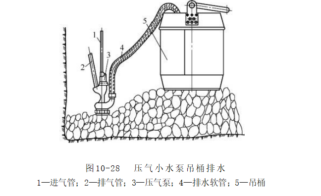
Bucket drainage has several distinct advantages. The equipment is simple—requiring no complex drainage system, just basic tools like buckets and small air-powered pumps—making it cost-effective. Operation is relatively straightforward, easy for construction workers to master. In cases involving small mines or shafts with minimal water inflow, bucket drainage can effectively meet basic drainage needs without occupying excessive shaft space, thus facilitating other ongoing construction activities inside the shaft.
Bucket drainage also has several limitations. Its drainage capacity is restricted by the bucket's volume and the number of lifting operations—both of which decrease as the wellbore depth increases, leading to a significant drop in overall drainage efficiency. Generally speaking, bucket drainage is only suitable for situations where the inflow rate is less than 8–10 m³/h. During the construction of a small vertical shaft, the initial inflow was relatively low, allowing bucket drainage to proceed smoothly. However, as excavation deepened and the water inflow gradually increased beyond the bucket's capacity, the working area became severely flooded, severely hampering construction progress. As a result, it became necessary to switch to an alternative drainage method. Moreover, bucket drainage requires manual operation of a small pneumatic pump, resulting in high labor intensity and relatively low drainage efficiency, making it difficult to meet the demands of large-scale, high-efficiency construction projects.
3.2 Submersible Pump Drainage
When the inflow rate in the shaft exceeds the drainage capacity of the bucket, using a hoisting pump for dewatering becomes a more suitable choice. A hoisting pump is a vertical-type pump with a relatively long body but a small horizontal cross-sectional area within the shaft. This unique feature gives it a distinct advantage in shaft equipment layout, enabling efficient use of shaft space and ensuring the smooth installation and operation of other construction equipment and facilities.
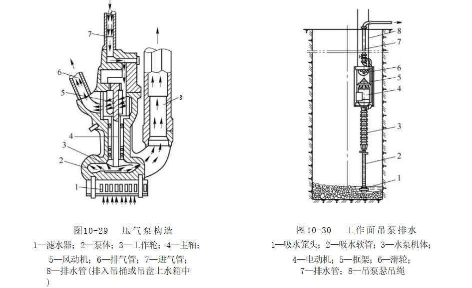
The submersible pump primarily consists of a suction nozzle, a suction hose, a pump body, an electric motor, a frame, pulleys, a discharge pipe, and a gate valve, among other components. Inside the well, the pump is suspended by a double rope, ensuring stable operation. The suction nozzle, positioned at the very bottom of the pump unit, serves to draw water from the working surface into the suction hose, which then transports the water directly to the pump body. The electric motor provides the necessary power to drive the pump's impeller at high speed, generating centrifugal force that propels water outward—from the center of the impeller toward its periphery—thereby creating a vacuum at the impeller's inlet. Under the pressure difference between atmospheric pressure and this negative pressure, water from the working surface flows into the pump chamber via the foot valve and suction hose. After passing through the impeller, the water gains energy and is subsequently directed through the discharge pipe’s bend, check valve, outlet connection, gate valve, discharge bend, expansion joint, and finally discharged to the ground via the drainage pipe.
Commonly used submersible pumps include the NBD model and the 80DGL multi-stage centrifugal pump. Different models vary in technical specifications such as pumping capacity, head, and motor power. For instance, the NBD30/250 submersible pump delivers a flow rate of 30 m³/h, with a head reaching up to 250 meters and a motor power of 45 kW. In contrast, the 80DGL50×15 model boasts a higher flow rate of 50 m³/h, a head that can soar as high as 750 meters, and an impressive motor power of 250 kW. These advanced technical parameters make them well-suited for meeting the drainage needs of vertical shafts under diverse conditions. In particular, for construction projects involving shafts with significant water inflow and considerable depth, it’s essential to select submersible pumps with higher heads and greater pumping capacities to ensure efficient removal of accumulated water from the shafts.
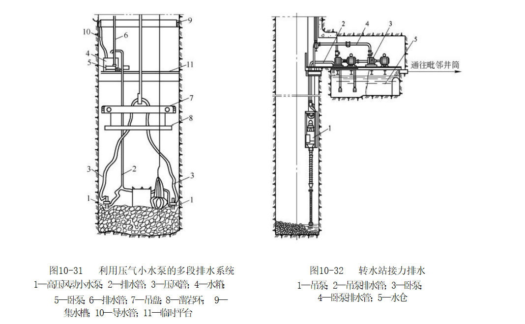
When the drainage depth in the shaft exceeds the lift capacity of a single hoisting pump, a relay drainage method becomes necessary. If the difference between the drainage depth and the pump's lift capacity is relatively small, compressed-air pumps can be used to transfer water from the working face directly to the hoisting platform or to temporary platforms equipped with water tanks, from where a hoisting pump or horizontal pump then discharges the water to the surface. For instance, during construction of a particular vertical shaft, the drainage depth surpassed the lift capacity of one hoisting pump by approximately 50 meters. To address this challenge, compressed-air pumps were installed at the working face to pump water into tanks on the hoisting platform. From there, a hoisting pump was employed to discharge the water from the tanks back to the surface, successfully resolving the drainage issue. However, when the drainage depth significantly exceeds the pump's lift capacity, it becomes essential to establish intermediate pumping stations (also known as "waist pump rooms") or transfer platforms at appropriate depths within the shaft. In such cases, the hoisting pump at the working face delivers water to the transfer station, where a horizontal pump then transports the water to the surface. If the main and auxiliary shafts are located relatively close to each other, they can even share a single transfer station. This is achieved by drilling a slightly inclined borehole connecting the two shafts, allowing water from one shaft to flow naturally through the borehole into the transfer station's reservoir in the other shaft—and ultimately being discharged to the surface as a whole. While this relay drainage approach does increase system complexity and construction costs, it effectively tackles the challenges associated with deep-shaft drainage, ensuring smooth progress throughout the vertical shaft construction process.
3.3 Other Drainage Methods (Such as drainage systems for intercepting and draining water seeping into the shaft during the operation and maintenance phase of new vertical shafts)
In addition to the traditional methods of bucket drainage and pump-based drainage, with continuous advancements in technology and deeper engineering practices, several innovative drainage technologies and devices have emerged. The new vertical shaft seepage and water-stop device, patented by China Railway Tunnel Bureau, offers a fresh approach and solution for draining water from vertical shafts during their operational phase.
This new device primarily consists of multiple sets of water-blocking bodies, each set comprising a receiving groove and two drainage grooves. Both the drainage grooves and the receiving groove are designed as segments of a circular ring with a hollow cavity structure, featuring open ends at their upper sections as well as at their front and rear extremities. In each set of water-blocking bodies, the two drainage grooves are arranged symmetrically and connected—through the receiving groove—to form a continuous pathway, while the bottom of the receiving groove is equipped with a drainage outlet. Multiple sets of these water-blocking bodies are installed inside the well shaft, closely adhering to the well walls, and are sequentially linked in a circular arrangement around the well wall, creating an overall ring-shaped structure. Additionally, the device includes cotton yarn, whose upper end is attached to the inner wall of the upper section of the well shaft, while the lower end extends down into the drainage and receiving grooves, effectively channeling seepage water from the well walls into the drainage and receiving grooves for efficient collection and removal.
Its working principle is based on an ingenious structural design. When the bottom plate of the drainage channel is placed at an angle inside the well shaft—tilted with the far end higher and the near end lower—this configuration facilitates the natural flow and collection of water. Meanwhile, the bottom plate of the receiving channel features an arc-shaped profile, with the convex side facing downward and positioned horizontally; its inner and outer widths match those of the drainage channel. The two ends of this bottom plate are seamlessly connected to the near ends of the bottom plates from the two adjacent drainage channels, further enhancing the efficiency of water guidance and collection. Additionally, between every pair of adjacent water-blocking units, the two drainage channels are linked via a connecting flow channel, which itself is shaped like a segment of a circular ring—a hollow structure with open tops as well as front and rear ends. The bottom plate of the connecting flow channel, meanwhile, curves upward along its arc, ensuring smooth water circulation throughout the entire device.
This new device boasts significant advantages. It effectively channels and drains seepage water from the shaft, minimizing the corrosive impact of wall-side runoff on structures and equipment, thereby extending the service life of the shaft. By filling the gaps between the inner panels of the receiving, drainage, and diversion channels and the shaft walls with polyurethane, the material expands upon contact with seepage water, completely sealing off any voids and reducing water flow. This prevents excessive seepage from spreading downward into non-seeping sections, significantly lowering the risk of erosion and scouring in those areas. Additionally, the device’s bottom plate is designed with a sloped profile, ensuring that seepage water flows smoothly into the system without causing blockages, thus enhancing drainage efficiency. Moreover, the device is crafted from synthetic resin materials, making it lighter, more corrosion-resistant, and highly durable—resulting in an extended lifespan. Finally, the use of wire mesh connected to pipes further secures the device in place, boosting its overall safety and reliability.
In the construction drainage method, first, multiple new-type devices are installed inside the well shaft, arranged at regular intervals both vertically and horizontally. Polyurethane is then filled between the inner plates of each device and the well wall. The upper end of cotton yarn is draped over the well wall above the devices, while the lower end extends down into the drainage groove and receiving trough—acting as a dedicated channel for water flow. Meanwhile, seepage from the well wall flows directly into the polyurethane, causing it to foam and expand, thereby completely sealing the gaps between the inner plates and the well wall, effectively minimizing downward water leakage. The second path of water follows the cotton yarn, eventually reaching the receiving trough, drainage groove, and finally the diversion groove. From there, the flowing water slopes downward toward the two drainage grooves on either side, collecting in the receiving trough before being discharged through a drain pipe into the adjacent lower-level device. At the very bottom, the final device directs the collected seepage water via another drain pipe straight to the well’s base.
Practical application results demonstrate that this new shaft maintenance-period water-sealing and drainage device has played a critical role in shaft drainage. In a specific shaft maintenance project, after implementing this device, seepage along the shaft walls was effectively controlled, significantly reducing corrosion of equipment and facilities. As a result, the operational safety and stability of the shaft were markedly improved, providing strong assurance for its long-term, reliable operation.
IV. Water-Control Methods for Shaft Tunnels
4.1 Water Blocking
During shaft construction, water interception is a critical water-control measure aimed at eliminating the impact of seepage water on the quality of the井壁 (well wall) and preventing deterioration of construction conditions, thereby ensuring smooth operations and maintaining the stability of the井壁. Depending on the specific stage of shaft construction and the nature of water inflow, water interception measures can be categorized into two types: temporary support-section water interception and permanent井壁 (well wall) leakage interception.
4.1.1 Water Leakage and Waterproofing Measures for Temporary Support Sections
When excavating the shaft wellbore, seepage along the temporary support section can significantly hinder construction if not effectively controlled. To address this issue, it is common to use either suspended plate flaps or water-stopping boards for interception.
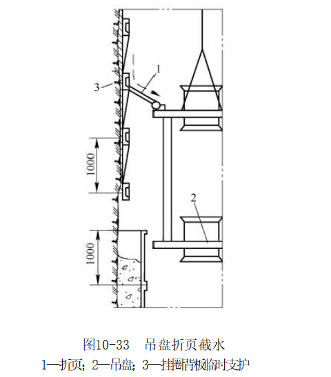
The hanging-plate folding method for water interception is a relatively common technique. Its structure primarily consists of folding plates, a hanging platform, and a temporary support system featuring a hanging-ring backboard. The folding plates are installed on the hanging platform; when water seeps into the shaft, it flows smoothly down the plates toward the bottom of the shaft, where it is then efficiently discharged through the existing drainage system. This method works by leveraging the倾斜 angle of the folding plates to guide the water flow, ensuring that it converges steadily at the shaft bottom for centralized drainage. During construction of a particular vertical shaft, the installation of hanging-plate foldings effectively captured and redirected seepage water from the temporary support section directly to the shaft bottom, significantly improving the working environment inside the shaft and accelerating the overall construction progress.
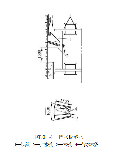
Water-stopping boards are also an effective temporary support measure for intercepting and diverting seepage water. Typically, a water-stopping board consists of wire, the board itself, wooden planks, and water-guiding strips. The wire secures the board in place, while the board directly blocks the flowing water. The wooden planks provide essential support and reinforcement, and the water-guiding strips direct the intercepted water downward toward the bottom of the well. In practical applications, the installation position and angle of the water-stopping board must be adjusted according to the specific seepage conditions, ensuring that it maximizes its water-interception efficiency. In areas where water inflow is particularly concentrated, properly installed water-stopping boards have successfully contained and diverted seepage, preventing it from affecting temporary supports and construction workers.
4.1.2 Permanent Wellbore Leakage and Waterstop Measures
Once the permanent shaft lining has been completed after the construction of the shaft, if severe water leakage occurs in the lining, more effective water-stop measures must be implemented. Commonly used methods include post-grouting or in-grouting behind the wall to seal off leaks, as well as installing fixed water-cutting grooves for water interception.
Backwall or in-wall grouting is a method that involves injecting grout into the voids between the well wall and surrounding rock, or directly into the well wall itself, to fill and seal off water leakage pathways. When performing backwall grouting, the first step is to identify the location and extent of the leakage points. Next, drill holes in the well wall and insert grouting pipes into these holes, then use a grouting pump to inject the slurry under pressure. Under this pressure, the grout fills the gaps between the well wall and the surrounding rock, creating an impermeable barrier that effectively stops water from leaking. In-wall grouting, on the other hand, targets cracks or pores within the well wall itself, enhancing its waterproofing performance. In one particular shaft, multiple leakage points were present along the well wall. By applying the backwall grouting technique—using both cement-based and chemical grouts—the team successfully sealed off the leaks, effectively controlling the water seepage throughout the well wall.
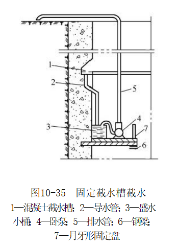
Fixed water cutoff trenches involve installing water-cutting channels directly into the permanent well walls, effectively capturing any remaining water and directing it either to a sump pump room or a water tank—where it can then be discharged back to the surface. Typically, these trenches are positioned below permeable layers and above areas in the sump pump room where water tends to accumulate. The structure of a typical water cutoff trench includes components such as a concrete channel, drainage pipes, a small collection bucket, a submersible pump, and a discharge pipe. The concrete channel collects leaking water, while the drainage pipes guide the water from the channel into the collection bucket. Finally, the submersible pump extracts the water from the bucket and pumps it through the discharge pipe, ultimately releasing it onto the ground. In one particular shaft, the installation of fixed water cutoff trenches has proven highly effective in intercepting and draining residual leaks from the well walls, thereby ensuring the smooth and uninterrupted operation of the shaft.
4.2 Drilling for Water Drainage
Drilling and drainage is a shaft-tunnel water-control method employed under specific conditions. It works by using boreholes to channel the inflowing water from within the shaft directly into the bottom-level roadway of an existing drainage system, thereby facilitating the discharge of groundwater and achieving the goal of dewatering the shaft.
When excavating shafts, borehole drainage is a highly effective water-control method if certain conditions are met. Once the bottom of the shaft is connected to a roadway and a dedicated drainage system has been established, a borehole can be drilled vertically downward through the shaft cross-section, directly reaching the bottom roadway. This allows the inflow of water inside the shaft to be efficiently discharged via the borehole into the bottom roadway, where it can then be removed using the existing drainage system. The key advantages of this approach include eliminating the need for hoisting pumps or pumping stations altogether, thereby simplifying the layout of equipment within the shaft and significantly reducing both capital investment and maintenance costs. Additionally, it improves working conditions inside the shaft by freeing up valuable space previously occupied by drainage equipment, providing construction personnel with more room to maneuver safely and comfortably. Moreover, the reduced noise levels and lower risk of safety hazards associated with operating heavy machinery further enhance the overall work environment. Furthermore, borehole drainage accelerates the construction process since there’s no longer a need for frequent installation, maintenance, or replacement of drainage equipment—streamlining the workflow and boosting efficiency. In scenarios such as mine reconstruction or expansion projects where conditions permit, borehole drainage should be prioritized as the preferred method for managing groundwater challenges.
To ensure the effectiveness of borehole drainage, it is essential to strictly control the quality of drilling. Drainage boreholes must be drilled precisely vertical, as any deviation could prevent water from flowing smoothly into the bottom-of-well roadway—or even lead to blockages. The degree of borehole deviation must remain within the confines of the shaft’s structural outline; otherwise, it may compromise the overall safety of the shaft. To safeguard the boreholes and prevent waste rock from clogging the drainage holes or causing the hole walls to collapse and seal the openings, a series of protective measures are typically implemented. For instance, a screened casing can be inserted into the borehole, providing both wall support and a mechanism to filter out impurities, thereby preventing cave-ins and blocking debris from entering the drill hole. As the working face advances, sections of the casing are gradually removed, ensuring that the borehole remains unobstructed at all times. Before blasting operations commence, the drainage holes must be sealed with wooden plugs to avoid blast-induced waste rock from jamming the openings. In some mines, when the borehole drainage method is carefully executed—with strict attention to verticality and robust protective measures in place—remarkable results have been achieved. Not only has this approach effectively addressed water-inrush issues, but it has also significantly enhanced both construction efficiency and overall project quality.
4.3 Grouting for Water Stopping
Grouting for water control is one of the key methods used to manage water in vertical shafts. It involves injecting specific grouting materials into the pores and fractures of the ground or井壁, allowing the slurry to spread, solidify, and harden, thereby creating an effective waterproof barrier that seals off water-inflow channels and significantly reduces water leakage. Grouting techniques for water control can be categorized into several types, including surface pre-grouting, face grouting, and post-grouting behind the wall—each with its own unique applications and advantages.
Ground pre-grouting involves drilling boreholes from the surface into the aquifers surrounding the shaft before shaft sinking begins. Grouting materials are then injected into these aquifers, creating an impermeable barrier that effectively prevents groundwater from flowing into the shaft. This method is particularly suitable for situations where aquifers are deep and water inflow rates are high. In the construction of a large vertical shaft, where the shaft would pass through multiple water-rich layers, ground pre-grouting was employed. Multiple boreholes were strategically arranged on the surface, extending deep into the aquifers, and a mixture of cement slurry and chemical grout was injected. After grouting, the water inflow from the aquifers was significantly reduced, providing ideal conditions for subsequent shaft excavation work. The primary advantage of ground pre-grouting is that it allows for proactive treatment of aquifers prior to shaft construction, eliminating the risk of water inflows disrupting the ongoing work. This not only enhances construction safety but also boosts efficiency. Additionally, this method can effectively seal off large areas of aquifers, delivering remarkably robust water-stopping results.
Face grouting is performed during shaft excavation when encountering aquifers or areas with significant water inflows—drilling and injecting grout directly into the working face. This method allows for prompt treatment of water-inflow points, offering targeted and effective solutions. During the construction of a particular vertical shaft, when excavation reached a certain depth, a major water surge suddenly emerged. At that moment, face grouting was immediately implemented: multiple boreholes were arranged on the working face, and fast-setting grouting materials were injected directly into the water-inflow zone, swiftly sealing off the channels and enabling construction to resume smoothly. The key advantages of face grouting lie in its ability to dynamically adjust grouting parameters and locations based on the actual water-inflow conditions, ensuring rapid and efficient resolution of water-related challenges. Additionally, this technique enables localized treatment of water surges without disrupting the overall progress of shaft construction, making it highly flexible and adaptable to varying site conditions.
Backwall grouting is performed after the井壁 (well wall) construction is completed, targeting the voids between the well wall and surrounding rock or cracks within the well wall itself, to enhance the wall's waterproofing performance. This method effectively seals off any water leakage points in the well wall, significantly improving its overall tightness. In one particular vertical shaft, after the well wall was finished, several water leakage issues were identified. To address this, backwall grouting was employed: holes were drilled into the well wall, and a mixture of cement slurry and micro-expansion materials was injected, filling the gaps between the wall and the surrounding rock while sealing the cracks. As a result, the well wall’s water leakage problem was completely resolved. The advantages of backwall grouting include its ability to provide comprehensive waterproofing treatment for the well wall, ensuring long-term protection against water ingress during extended use. Additionally, it can effectively repair existing leakage issues, thereby extending the service life of the well wall.
Different grouting and water-stopping measures can be combined based on specific site conditions in practical applications to achieve the best water-control效果. In some complex geological settings, a single grouting method may not fully address water-inrush issues. Therefore, it’s advisable to first implement ground pre-grouting to provide an initial barrier against aquifers, followed by working-face grouting during shaft excavation to tackle localized water inflows. Finally, after the shaft lining is completed, back-wall grouting can be used to further enhance the waterproofing performance of the shaft walls. This integrated approach allows for the full utilization of each grouting method’s strengths, significantly improving the overall water-stopping efficiency. For instance, in the construction of a vertical shaft under particularly challenging geological conditions, the above-mentioned combined grouting technique was employed, resulting in a water-stopping rate exceeding 95%. This innovative solution effectively resolved the water-inrush problem, ensuring smooth construction progress and long-term stable operation of the shaft.
V. Technical Challenges and Solutions for Shaft Drainage and Water Control in Vertical Shafts
5.1 Technical Challenges
In the process of shaft drainage and water control, complex geological conditions pose the primary challenge. The lithology of the strata is intricate and highly variable, with significant differences in permeability and mechanical properties among rocks of different types. This makes it particularly difficult to accurately identify the sources and volumes of groundwater inflows. During the construction of a certain shaft, the shaft wall passed through a variety of strata, including sandstone, shale, and limestone. While sandstone exhibits high permeability, shale acts as a relatively effective barrier against water flow, and limestone may contain dissolved caves and fractures. Such a complex lithological combination has resulted in exceptionally complicated groundwater dynamics, presenting formidable challenges for both drainage and water-control operations.
Fault fractures are also a common issue. These faults and fractures provide pathways for groundwater flow, significantly increasing the uncertainty of water inflows. When a shaft penetrates through fault or fracture zones—especially areas with high fault density—the volume of water influx can suddenly surge, and the direction of the flow becomes difficult to predict. In one mine shaft construction project, an accurately undetected concealed fault led to a sudden and massive water inflow as excavation reached that specific area. The inflow rate instantly jumped from the original 20 m³/h to 80 m³/h, forcing construction to halt abruptly and severely impacting both project timelines and safety conditions.
High groundwater levels also pose significant challenges for drainage and flood control. Elevated water levels mean greater water pressure, which increases both the pressure and flow rate of any emerging water, thereby placing higher demands on the lift height and capacity of drainage equipment. In some plain regions, during shaft construction, the groundwater level is so close to the surface that builders must contend with immense water pressure as they excavate the shaft, making drainage operations exceptionally difficult.
Drainage equipment also faces challenges in terms of head, flow rate, and operational stability. As the depth of vertical shafts increases, the required head for drainage systems becomes increasingly demanding—yet currently, some existing drainage devices struggle to meet the high-head requirements of ultra-deep shafts. Additionally, the flow rate of drainage equipment must be adjusted appropriately according to fluctuations in water inflow; otherwise, it could lead to delayed drainage or even equipment overload. Operating in the harsh underground environment, drainage systems must also demonstrate exceptional stability and reliability to ensure long-term, uninterrupted performance. During construction of a particularly deep vertical shaft, insufficient head from the drainage equipment prevented water from being pumped effectively to the surface. As a result, engineers had to resort to a relay-based drainage method, significantly increasing both the complexity and cost of the overall system.
During the implementation of water-control measures, technical challenges often arise. For instance, when grouting to stop water inflow, it is difficult to precisely control the diffusion range and solidification effect of the grout mixture. If the grout spreads unevenly, some water-entrance channels may remain unsealed; conversely, if the grout takes too long or too little time to solidify, the water-stopping performance could be compromised. In a particular vertical shaft grouting project aimed at waterproofing, improper control of the grout's setting time led to water leakage in certain grouted areas, ultimately requiring a second round of grouting—resulting in increased project costs and an extended construction timeline.
5.2 Solution Exploration
For complex geological conditions, it is essential to employ advanced exploration and monitoring technologies. By utilizing geophysical methods such as 3D seismic exploration and transient electromagnetic techniques, we can more accurately detect information like stratigraphic lithology and the distribution of faults and fractures, providing a reliable basis for developing effective water-control strategies. Real-time monitoring of groundwater levels, water pressures, and discharge volumes allows for timely adjustments to drainage and water-control measures. In the construction of a vertical shaft under particularly challenging geological conditions, the application of 3D seismic exploration technology enabled precise identification of fault and fracture locations in advance, offering critical insights that facilitated the development of a targeted water-control plan—and ultimately helped prevent a potential water-inrush incident.
Optimizing the selection and configuration of drainage equipment is also crucial. Based on parameters such as shaft depth, water inflow rate, and water pressure, choose drainage equipment with appropriate head and flow capacity, and properly equip it with backup units to ensure the reliability of the drainage system. Additionally, implementing an intelligent control system enables remote monitoring and automatic adjustment of the drainage equipment, dynamically fine-tuning operational parameters in response to changes in water inflow. For instance, in a certain shaft drainage system, the installation of an intelligent control system allows the system to automatically adjust the speed and number of operating pumps whenever water inflow fluctuates, thereby maintaining efficient and stable operation while significantly reducing energy consumption.
Improving water-control techniques and materials can also effectively address technical challenges. By developing new grouting materials, we can enhance the fluidity, setting strength, and durability of the grout, thereby boosting its water-stopping performance. Additionally, refining the grouting process—such as implementing directional grouting and segmented grouting techniques—allows for precise control over the injection location and the extent of grout diffusion. In a recent vertical shaft water-control project, the use of innovative chemical grouting materials combined with advanced directional grouting technology successfully sealed off intricate water-inflow channels, significantly reducing the volume of water seeping into the shaft and ensuring smooth construction progress.
6. Summary
Drainage and water control in shafts are critical components of mining engineering, as their success directly impacts the safety, schedule, quality, and cost of the entire mining project. Through an in-depth analysis of the hazards posed by water inflows in shafts, we clearly recognize that such inflows not only deteriorate working conditions and threaten the safety of construction personnel but also severely compromise the integrity of the shaft walls. This, in turn, can lead to significant delays in project timelines, skyrocketing costs, and even potentially trigger catastrophic flooding incidents—resulting in immense losses for the mine.
To effectively address these issues, thorough preparatory work is especially critical. Exploratory drilling allows for a detailed understanding of the properties, structures, and hydrological conditions of the rock layers through which the shaft passes, providing crucial insights that inform the development of a scientifically sound and well-planned water-control strategy. During the drainage and water-control process, various drainage methods and techniques are carefully integrated, leveraging their respective strengths. Bucket-based drainage is ideal for situations with relatively low water inflows, offering simplicity in equipment and ease of operation; submersible pump drainage, on the other hand, proves indispensable when dealing with higher water volumes, efficiently meeting the demands of deep-well drainage. Moreover, the application of innovative technologies—such as advanced vertical-shaft maintenance systems designed to intercept and seal shaft seepage—has further enhanced both drainage efficiency and water-control effectiveness. Techniques like water interception, borehole drainage, and grouting-based water-stopping methods are tailored to specific geological conditions and water-inflow scenarios, enabling precise control of groundwater flow and ensuring the safety of both shaft construction and ongoing operations.