

-
About Us
-
-
-
Contact Us

Shaft bottom yard - Black King Kong broadcast
I. Introduction
(Image from MOOC Northeastern University Underground Mining of Metal Deposits Xu Shuai, An Long )
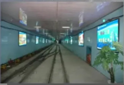
The bottom station connects underground transportation with shaft hoisting, hoisting ore, waste rock, and sending down materials and equipment, all of which must be transported through here. Therefore, storage lines, shunting lines, and detours must be set up near the shaft; for personnel lifting, drainage, and ventilation, some chambers must be set up near the shaft, such as: pump rooms, water tanks, underground substations, waiting rooms, etc. The bottom station is the general term for these roadways and chambers. The bottom station connects underground transportation with shaft hoisting, hoisting ore, waste rock, and sending down materials and equipment, all of which must be transported through here. Therefore, storage lines, shunting lines, and detours must be set up near the shaft; for personnel lifting, drainage, and ventilation, some chambers must be set up near the shaft, such as: pump rooms, water tanks, underground substations, waiting rooms, etc. The bottom station is the general term for these roadways and chambers.
In the vast system of mining operations, the vertical shaft bottom station acts as a crucial hub, occupying an indispensable core position. It is the key link connecting vertical shaft hoisting and underground transportation, shouldering the heavy responsibility of transporting ore, waste rock, personnel, materials, and equipment. It is the transportation hub and dispatching center of the entire mining process. From here, the ore is efficiently transported to the surface, opening up subsequent processing and utilization; personnel, materials, and equipment can also smoothly reach various work sites underground, ensuring the orderly progress of mining work; while the waste rock is properly transported out through the bottom station, maintaining the cleanliness and safety of the underground working space. It can be said that the efficiency of the vertical shaft bottom station directly affects the efficiency and cost of mining operations, affecting the economic benefits and production safety of the mine. Therefore, in-depth exploration of the relevant knowledge of the vertical shaft bottom station is of great significance for optimizing mining operation processes and improving mine production levels. This article will comprehensively analyze the lines, chambers, classification of forms, and selection factors of the vertical shaft bottom station, providing useful references for the practice of mining engineering.
(Image from MOOC Northeastern University Underground Mining of Metal Deposits Xu Shuai, An )
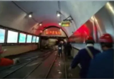
II. Understanding the Vertical Shaft Bottom Station
As a key hub in mine mining, the vertical shaft bottom station is a collection of special roadways and chambers connecting the main hoisting shaft and the main underground transportation and ventilation roadways of the mine. It is like the heart of the human body, playing a crucial connecting role in the entire mining system. It is the key link connecting the two core production links of shaft hoisting and underground transportation, and it is also the general hub station for underground transportation, shouldering the heavy responsibility of transporting ore, waste rock, personnel, materials, and equipment, and playing a decisive role in the efficient and safe operation of the entire mine.
(Image from MOOC Northeastern University Underground Mining of Metal Deposits Xu Shuai, An Long )
(1) Line Composition
1. Storage lines : Similar to parking spaces in a large parking lot, storage lines are mainly used to store empty and loaded vehicles, and are areas where various vehicles are temporarily parked. It includes the heavy vehicle line and empty vehicle line of the main shaft, where loaded vehicles carrying ore from the underground mining area are parked, as well as empty vehicles waiting to be loaded again after unloading; the heavy vehicle line and empty vehicle line of the auxiliary shaft, in addition to transporting ore, the auxiliary shaft also undertakes the task of transporting personnel, materials, and equipment, so the types of vehicles on its heavy vehicle line and empty vehicle line are more diverse; in addition, there are special material branch lines for parking material vehicles, which carry various materials needed for underground production, such as support materials, mechanical equipment parts, etc. The setting of material branch lines facilitates the storage and use of materials.
2. Travel lines : If the storage lines are the parking spaces in the parking lot, then the travel lines are the passages in the parking lot. The travel lines are the lines for scheduling the operation of empty and loaded vehicles, and are the passages for vehicles to travel in the bottom station. They are like the main roads and branch roads in urban traffic, ensuring that vehicles can travel and be scheduled in an orderly manner. The detours connecting the empty and loaded vehicle lines of the main and auxiliary shafts are like the ring roads in the city, allowing vehicles to travel smoothly between the main and auxiliary shafts, avoiding traffic congestion; the shunting yard branch lines are specifically used for vehicle scheduling and grouping, where vehicles can perform uncoupling, coupling, and turning operations to meet different transportation needs; the headframe line is the key passage for mine cars to enter and exit the skip, it is directly connected to the shaft, and is the only way for personnel, materials, and equipment to enter and exit the shaft, its importance is self-evident.
(2) Chamber Composition
1. Main shaft system chambers : The main shaft system chambers are a series of chambers arranged around the main shaft, and they together constitute a highly efficient ore hoisting and processing system. The tipping chamber is an important place for ore unloading, where ore-laden mine cars unload ore into chutes or ore bins through tipping equipment; the ore bin is used to temporarily store ore, playing a buffering and regulating role in ore transportation, ensuring that even if there is a malfunction of the hoisting equipment or uneven transportation, there is still a place to store the ore; the skip loading chamber is where the ore in the ore bin is loaded into the skip, and through precise loading equipment, the ore is quantitatively loaded into the skip for hoisting to the ground; the cleaning and ore scattering chamber and inclined shaft are used to clean up the ore scattered during ore transportation and hoisting, preventing ore accumulation from affecting production, and also recovering valuable mineral resources.
2. Auxiliary shaft system chambers : The auxiliary shaft system chambers mainly serve the transportation of personnel, materials, and equipment, as well as important functions such as mine drainage and power supply. The headframe is the key connection between the auxiliary shaft and the bottom station roadway, and is also the throat for personnel, materials, and equipment to enter and exit the shaft. It is equipped with operating equipment such as a rocker, a pusher, and a brake, ensuring that vehicles can safely and accurately enter and exit the skip; the pump room and substation are important power and drainage facilities for the mine. The pump room is equipped with various drainage equipment, responsible for draining the accumulated water underground to ensure the safety of the underground working environment, and the substation provides power supply for the entire mine, ensuring the normal operation of various equipment; the water tank is used to store underground water inflow, through sedimentation and filtration, separating impurities such as mud and sand from the water inflow, and then discharging it by pump, ensuring the normal operation of the drainage system; the waiting room is where miners wait to take the skip, providing miners with a relatively comfortable and safe waiting environment.
3. Other chambers In addition to the main and auxiliary shaft system chambers, the bottom station also has other chambers to meet the various needs of mine production and management. The dispatch room is the command center of the bottom station, equipped with telecommunications and electrical equipment. Dispatchers can monitor the operation of underground vehicles in real time, command vehicle dispatch and driving, and ensure efficient transportation; the electric locomotive garage and locomotive repair chamber are used for parking and repairing underground electric locomotives. Electric locomotives are one of the main tools for underground transportation, and their normal operation is crucial for mine production. Therefore, the setting of the electric locomotive garage and locomotive repair chamber can timely maintain and repair electric locomotives, ensuring their performance and safety; in addition, according to the actual needs of the mine, there may also be fire doors, explosive warehouses, fire materials warehouses, etc. These chambers play an important role in mine safety protection and emergency handling.
III. Types of Vertical Shaft Bottom Stations
(1) Classification by hoisting equipment
1. Skip bottom station Using skips as hoisting containers, mainly used for hoisting personnel, materials, equipment, and a small amount of ore and waste rock. The hoisting characteristics of skips determine that the layout of the skip bottom station is more flexible and can adapt to different mine conditions and production needs. Its line layout is usually relatively simple, and the setting of the storage line and shunting line is relatively concentrated, which is convenient for operation and management. Skip bottom stations are widely used in small mines or as auxiliary shaft hoisting systems because they can easily realize the up and down transportation of personnel and materials, meeting the needs of auxiliary hoisting in mines.
2. Skip bottom station Using skips as hoisting containers, mainly used for hoisting a large amount of ore. Skips have the advantages of large hoisting capacity and high speed, so the design of skip bottom stations pays more attention to the efficient transfer of ore. Its main shaft system chambers are relatively complex, including tipping chambers, ore bins, skip loading chambers, etc., to realize the unloading, storage, and loading of ore. Skip bottom stations are suitable for large and medium-sized mines with high output, which can meet the needs of large-scale ore hoisting and improve mine production efficiency.
3. Skip - Skip and cage combined bottom station Combining the characteristics of skip and cage hoisting equipment, there is a skip system for hoisting ore and a cage system for hoisting personnel, materials, and equipment. This type of bottom station can give full play to the advantages of the two hoisting equipment and realize the integration of multiple functions. The layout of its lines and chambers is more complex, and it is necessary to reasonably plan the running lines of the two hoisting equipment and the location of related chambers to ensure the efficient operation of the entire system. Skip - Skip and cage combined bottom stations are usually used in some large-scale mines with complex production processes, which can meet the various needs of ore hoisting and auxiliary hoisting.
(2) Classification by the number of shafts served
1. Single-shaft bottom station Only serves one shaft, and the layout of its lines and chambers is centered around that shaft. This type of bottom station has a relatively simple structure, small project volume, and low construction cost. Because it only serves one shaft, its hoisting capacity and transportation capacity are relatively limited, suitable for small mines or some auxiliary shafts. In small mines, single-shaft bottom stations can meet the basic production needs of the mine while reducing construction and operating costs.
2. Multi-shaft bottom station Serves multiple shafts, commonly a main and auxiliary shaft combined bottom station. The main shaft is responsible for ore hoisting, and the auxiliary shaft is responsible for hoisting personnel, materials, and equipment, as well as transporting waste rock. The layout of lines and chambers in multi-shaft bottom stations needs to consider the coordination and cooperation between multiple shafts to achieve efficient transportation and hoisting. Its throughput is large, which can meet the production scale and output requirements of large and medium-sized mines. In large and medium-sized mines, multi-shaft bottom stations can give full play to the advantages of each shaft and improve the overall production efficiency of the mine.
(3) Classification by mine car running system
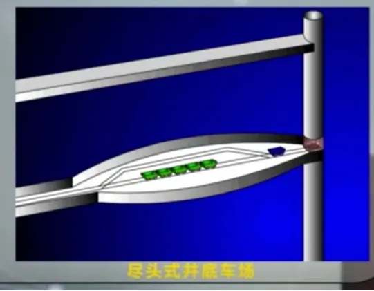
1. Dead-end bottom station It has the characteristics of single-sided entry and exit of the shaft. The storage lines and marshalling yards for empty and loaded cars are located on one side of the shaft. This type of bottom station has a simple line layout and low construction cost, but its throughput is small. When it is necessary to pull out the empty car from the cage, the loaded car can be pushed in. This process is relatively cumbersome, resulting in a slow turnover speed of vehicles. Dead-end bottom stations are suitable for small mines or auxiliary shafts because the transportation volume is relatively small in these cases, and the requirements for throughput are not high.
(Image from MOOC Northeastern University Underground Mining of Metal Deposits Xu Shuai, An Long )
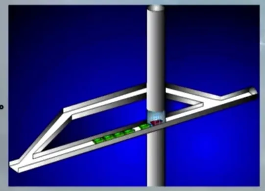
2. Loop bottom station Lines are laid on both sides of the shaft or unloading equipment. Loaded cars enter on one side, and empty cars exit on the other side. Empty cars return via another parallel line or change direction from the original line. The throughput of loop bottom stations is higher than that of dead-end stations because it realizes the simultaneous entry and exit of loaded and empty cars, reducing vehicle waiting time. When the rock is stable, parallel loop lines can be laid in the same roadway, which can save roadway development work; if the rock is unstable, parallel roadways need to be excavated separately. This type of bottom station is suitable for mines with moderate output, which can better balance transportation efficiency and construction cost.
(Image from MOOC Northeastern University Underground Mining of Metal Deposits Xu Shuai, An Long )
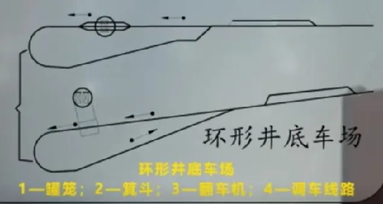
3. Loop bottom station Empty cars coming out of the shaft or unloading equipment form a loop line by detouring back. Its shunting work is relatively simple, and vehicles can run continuously on the loop line, reducing shunting time, thereby achieving a large throughput. The development work of loop bottom stations is large because it is necessary to excavate a special detour to form a loop line. It is suitable for large and medium-sized mines with large output, which can meet the needs of large-scale transportation and improve mine production efficiency.
(Image from MOOC Northeastern University Underground Mining of Metal Deposits Xu Shuai, An Long )
IV. Lines and Chambers of Vertical Shaft Bottom Stations
(1) Line Composition
1. Storage lines The storage lines play an indispensable role in the shaft bottom yard, primarily storing various empty and loaded vehicles. The main shaft's loaded vehicle line carries vehicles returning from the underground mine filled with ore, temporarily parking them here before unloading and hoisting operations. The main shaft's empty vehicle line parks empty vehicles that have finished unloading and are ready to return to the mine for loading. The secondary shaft's loaded and empty vehicle lines are equally important. The secondary shaft not only transports ore but also personnel, materials, and equipment. Therefore, its loaded vehicle line may park vehicles carrying equipment or materials, while the empty vehicle line provides parking space for empty vehicles returning from the shaft. The material branch line is specifically for parking material vehicles carrying various supplies needed for underground production, such as steel and timber for support, and parts for various mechanical equipment. The material branch line allows for centralized parking of material vehicles, facilitating management and dispatch to ensure materials can be quickly transported to various underground work sites when needed.
2. Travel lines The haulage lines are the traffic arteries of the shaft bottom yard, responsible for scheduling the operation of empty and loaded vehicles. The bypass connecting the main and secondary shaft's empty and loaded vehicle lines, like a ring road in urban traffic, allows vehicles to smoothly travel between the main and secondary shafts, avoiding traffic congestion caused by line intersections and significantly improving vehicle operating efficiency. The marshalling yard branch line is an important location for vehicle scheduling and grouping. Here, locomotives can perform operations such as uncoupling, coupling, and turning vehicles, combining different types of vehicles into suitable trains based on transportation needs to meet the diverse needs of underground transportation. The headframe line is the key passage for mine cars entering and exiting the skip. It is directly connected to the shaft and is the only way for personnel, materials, and equipment to enter and exit the shaft. The headframe line is equipped with operating equipment such as turntables, pushers, and car stoppers, which work together to ensure mine cars can safely and accurately enter and exit the skip, achieving efficient transportation between the shaft and the bottom yard.
(II) Chamber Layout
1. Main shaft system chambers The main shaft system chambers are closely arranged around the main shaft, cooperating to complete ore hoisting and processing tasks. The skip dumping chamber is the core location for ore unloading. Mine cars filled with ore enter the skip dumping chamber, and the ore is dumped into the chute or ore bin through the skip dumping equipment, separating the ore from the mine cars. The ore bin is a temporary storage space for ore, playing an important role in buffering and regulating ore transportation. When hoisting equipment malfunctions or transportation is unbalanced, the ore bin can store excess ore, preventing ore from accumulating on the transportation lines and affecting normal production. When the hoisting equipment runs smoothly, the ore bin can promptly supply ore to the skip loading chamber, ensuring the continuity of hoisting operations. The skip loading chamber is the key area for loading ore from the ore bin into skips. Through precise loading equipment, ore is loaded into skips in a fixed quantity according to the specified weight, ensuring the stability and safety of the skips during hoisting. The ore cleaning and spillage chamber and incline are used to clean up ore spilled during ore transportation and hoisting. If this spilled ore is not cleaned up promptly, it will not only cause resource waste but also affect the normal operation of the shaft bottom yard. The ore cleaning and spillage chamber and incline use special equipment and passages to collect the spilled ore and transport it to a designated location for resource recycling.
2. Auxiliary shaft system chambers The secondary shaft system chambers mainly serve the transportation of personnel, materials, and equipment, as well as important functions such as mine drainage and power supply. The headframe, as the key connection between the secondary shaft and the shaft bottom yard roadway, is the gateway for personnel, materials, and equipment to enter and exit the shaft. The turntables, pushers, and car stoppers installed inside work together to ensure vehicles can safely and accurately enter and exit the skip. When the skip reaches the bottom of the shaft, the turntable lowers and connects with the skip, the pusher pushes the mine car out of the skip, and the car stopper prevents accidental sliding of the mine car, ensuring safe and reliable transportation. The pump room and substation are important power and drainage facilities for the mine. The pump room is equipped with various drainage equipment, such as pumps and pipes, responsible for draining accumulated water from the underground to ensure a safe underground working environment. During mining, groundwater continuously flows into the underground. If not drained promptly, it will submerge roadways and mining areas, endangering personnel and equipment. The substation provides power to the entire mine, converting high-voltage power into low-voltage power suitable for underground equipment through transformers and switchgears, ensuring the normal operation of various equipment. The water tank stores underground water. Through sedimentation and filtration, it separates impurities such as silt from the water, which is then drained by pumps. The reasonable design and effective operation of the water tank can ensure the normal operation of the drainage system and prevent underground water accumulation from affecting production. The skip waiting room is where miners wait to board the skip, providing a relatively comfortable and safe waiting environment. The skip waiting room usually has seats and lighting equipment to facilitate miners' rest and waiting. It is also equipped with safety facilities and communication equipment to ensure that miners can be notified and appropriate measures taken in emergencies.
V. Selection of Shaft Bottom Yard Type
The selection of the shaft bottom yard type is a comprehensive decision-making process that requires consideration of numerous factors to ensure it meets the various needs of mine production and achieves efficient, safe, and economical operation.
(I) Key Influence of Production Capacity
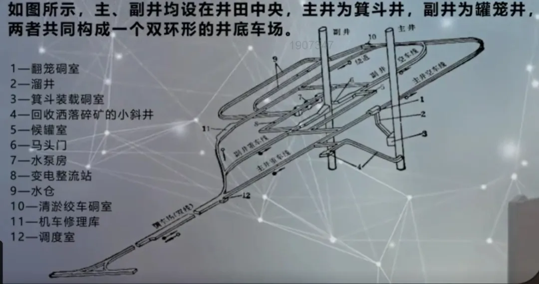
Mine production capacity is one of the core factors determining the type of bottom yard. For large and medium-sized mines with high annual output, it is usually necessary to design main and secondary shafts to meet large-scale hoisting and transportation needs. The main shaft often uses skips for efficient hoisting of large quantities of ore, while the secondary shaft uses cages for transporting personnel, materials, and equipment. In this case, the main and secondary shaft systems often use a ring-shaped layout, forming a double-ring bottom yard. This is because the ring-shaped bottom yard has a higher throughput capacity, capable of handling the operation and scheduling of a large number of vehicles, meeting the production scale and output requirements of large and medium-sized mines. For smaller mines with lower output, due to the relatively small transportation volume and lower throughput capacity requirements for the bottom yard, a simpler dead-end or loop-type bottom yard can be chosen. These yard types have lower construction costs, meeting production needs while reducing mine construction and operating costs.
(II) Guiding Role of Hoisting Container Type
The choice of hoisting container type directly guides the selection of the bottom-of-shaft yard form. Cage hoisting is mainly used for transporting personnel, materials, and equipment, as well as a small amount of ore and waste rock. The advantage of cage hoisting is its higher flexibility, adapting to different transportation needs, but its hoisting capacity is relatively small. Therefore, when cage shafts are used for main and auxiliary shaft hoisting, a circular yard is generally adopted. A circular yard can provide a smoother running route for the cage, facilitating vehicle scheduling and entry and exit. However, if the surrounding rock is unstable and the mine's production capacity is small, and a detour can be directly laid out near the outside of the shaft, a return yard can also be considered. In this case, a return yard can reduce the amount of roadway development work and lower construction costs. Skip hoisting is mainly used for hoisting large quantities of ore, with the advantages of large hoisting volume and speed. When skip hoisting is used for ore, the choice of transportation method will affect the yard form. When using side-discharge mine cars for transportation, if the transportation volume is small, a return yard is often used; if the transportation volume is large, a circular yard can be used to reduce the time for detaching and attaching operations. When using double-locomotive-hauled bottom-discharge mine cars, a return yard is often used. This is because a return yard can better adapt to the unloading and shunting requirements of bottom-discharge mine cars, improving transportation efficiency.
Adaptability of Transportation Equipment and Shunting Methods
There needs to be high adaptability between transportation equipment and shunting methods and the bottom-of-shaft yard form. In terms of transportation equipment, different types of mine cars have different requirements for the layout of the bottom-of-shaft yard lines and shunting methods. Fixed mine cars often utilize locomotive reversing to push and top car groups for direct unloading in a dead-end yard. This is because the unloading method of fixed mine cars is relatively simple, and the line layout of the dead-end yard can meet its shunting and unloading needs. Bottom-discharge mine cars, due to their special unloading method, cannot have their head and tail reversed during shunting, so they mostly use return-type bottom-of-shaft yards. The line structure of the return yard allows bottom-discharge mine cars to travel back and forth on two tracks in the same roadway, facilitating unloading and shunting. In terms of shunting methods, different bottom-of-shaft yard forms also have their own characteristics. The shunting work of a circular bottom-of-shaft yard is relatively simple, and vehicles can run continuously on the circular line, reducing shunting time and thus achieving a larger throughput capacity. However, it has many roadway intersections and many large-radius curve roadways, making construction complex, with a large amount of excavation work, slow speed of electric locomotives on bends, and poor safety in top-push shunting. In a return-type bottom-of-shaft yard, empty and loaded trains can travel back and forth on two tracks in the same roadway within the yard, simplifying the line structure of the bottom-of-shaft yard and reducing the amount of roadway excavation work. However, its roadway cross-section is large, and construction and support are more complex. The line layout of a dead-end bottom-of-shaft yard is simple, and the construction cost is low, but the throughput capacity is small, suitable for small mines or auxiliary shafts. Therefore, when choosing a bottom-of-shaft yard form, it is necessary to consider various factors comprehensively based on the type of transportation equipment and the characteristics of the shunting method, and choose the most suitable yard form.
Influence of the Number and Layout of Shafts
The number of shafts and their relative positions have an important impact on the layout of the bottom-of-shaft yard form. A single-shaft bottom-of-shaft yard only serves one shaft, and its lines and chambers are arranged around that shaft. This bottom-of-shaft yard structure is relatively simple, with a smaller amount of work and lower construction costs. However, since it only serves one shaft, its hoisting capacity and transportation capacity are relatively limited, suitable for small mines or some auxiliary shafts. A multi-shaft bottom-of-shaft yard serves multiple shafts, commonly a main and auxiliary shaft combined bottom-of-shaft yard. The main shaft is responsible for ore hoisting, and the auxiliary shaft is responsible for hoisting personnel, materials, and equipment, as well as transporting waste rock. The line and chamber layout of a multi-shaft bottom-of-shaft yard needs to consider the coordination and cooperation between multiple shafts to achieve efficient transportation and hoisting. Its throughput capacity is larger, able to meet the production scale and output requirements of large and medium-sized mines. In a main and auxiliary shaft combined bottom-of-shaft yard, the relative positions of the main and auxiliary shafts will also affect the choice of yard form. If the main and auxiliary shafts are close together, a horizontal or shuttle yard can be chosen; if they are far apart, a vertical, knife-type, or dead-end yard can be chosen. In addition, it is necessary to consider the relative positions of the shafts and the main transportation roadways to ensure a smooth connection between the bottom-of-shaft yard and the underground transportation system.
Design Key Points for Vertical Shaft Bottom-of-Shaft Yards
Design Basis
1. Mine Design Production Capacity and Work System This is the basic data for the design. The mine's design production capacity determines the amount of ore, waste rock, and materials that the bottom-of-shaft yard needs to handle, as well as the personnel lifting needs. The annual working days, daily working shifts, and production shifts, etc., affect the operating intensity and running time of the bottom-of-shaft yard at different time periods. 100 ten thousand tons per year, according to annual working days 300 days, daily work 3 shifts, each shift produces 6 hours of calculation, the bottom-of-shaft yard needs to complete the ore hoisting and transportation tasks within the corresponding time, which requires the yard's lines and equipment to meet such production scale and time requirements.
2. Mine Development Method This includes the location, form, and mutual relationship of each shaft, the relationship between the main roadways, main gate, and shaft, the azimuth of the roadways near the yard, etc. These factors determine the connection method and layout between the bottom-of-shaft yard and the shaft and roadways. When the shaft is located in the center of the mining area, and the main roadways connect vertically with the shaft, this development method will affect the line direction and chamber layout of the bottom-of-shaft yard, requiring it to be reasonably planned around the shaft and roadways.
3. Shafts and Number of Shafts The purpose and plan and cross-section layout of the shafts, the type, characteristics, specifications, and relevant dimensions of the hoisting containers, the loading method of the main hoisting, etc. Shafts with different purposes, such as the main shaft used for hoisting ore and the auxiliary shaft used for hoisting personnel, materials, and equipment, have different design and layout requirements. The type and size of the hoisting container will also affect the line and chamber design of the bottom-of-shaft yard. When using skip hoisting for ore, the capacity and external dimensions of the skip will determine the size and shape of the skip loading chamber.
4. Mine Main Transportation Roadway Transportation Method Transportation methods and their equipment, such as the specifications and characteristics of electric locomotives, mine cars, belt conveyors, etc., the maximum outer edge dimensions of the equipment, train composition, mine car connection method, waste rock output and handling method, timber and other material quantities, handling method of excavated coal, transportation method of underground personnel, etc. These factors are directly related to the transportation capacity and operation process of the bottom-of-shaft yard. When using electric locomotives to haul mine cars, it is necessary to consider the running speed and traction force of the electric locomotives, as well as the number and connection method of the mine cars, to determine the line gradient and length of the bottom-of-shaft yard.
5. Mine Methane Grade and Ventilation Method Mine gas level and gas emission, intake (exhaust) air volume of the shaft, air distribution of each wing, air volume passing through each roadway of the bottom station, etc. Gas level and ventilation method affect the design and safety measures of the bottom station ventilation system. High-gas mines require stricter ventilation requirements and gas monitoring equipment to ensure the safe operation of the bottom station.
6. Layout of the mine surface and underground production system The operating system at the connection between the cage shaft and the bottom station, the capacity of the tippler (unloading station), the capacity of the coal bin, etc. The layout of the surface and underground production system determines the connection and coordination between the bottom station and other production links. The design of the operating system at the connection between the cage shaft and the bottom station needs to consider the speed and safety of the cage entering and leaving.
7. Relevant information of various chambers Such as the purpose, size, and equipment layout of the chamber. Different chambers have different functions and requirements. The pump room needs to consider the installation and operation space of the drainage equipment, and the substation needs to meet the safety protection and heat dissipation requirements of the electrical equipment. This information is crucial for the reasonable layout and design of the bottom station chambers.
8. Geological conditions, hydrogeological conditions, and mine water inflow at the location of the bottom station Geological conditions affect the stability and construction difficulty of the roadways and chambers of the bottom station. If the rock at the location of the bottom station is loose, fragmented, or has unfavorable geological conditions such as faults and strong aquifers, special support and waterproof measures need to be taken. The mine water inflow will affect the design of the drainage system of the bottom station to ensure that the accumulated water can be discharged in time to ensure production safety.
(2) Design Requirements
1. Abundant Throughput Capacity The abundant throughput capacity of the bottom station should be greater than 30 % of the mine's designed production capacity. This is to cope with possible fluctuations in production, equipment failures, etc., during the mine production process, ensuring that the bottom station can meet the normal production needs of the mine. When there are two coal transportation equipment, belt conveyor and mine car, transporting coal to a bottom station, the abundant throughput capacity of the mine car transportation part of the bottom station should be greater than 30 % of the designed production capacity of the mine car transportation part. This can ensure that the bottom station has sufficient transportation capacity under different transportation methods.
2. Production Increase Possibility The possibility of increased production should be considered when designing the bottom station. With the development of the mine and technological advancements, the mine may increase its production capacity. Therefore, when designing the bottom station, it is necessary to reserve a certain amount of development space, such as increasing the line length and expanding the chamber capacity, so that it can be easily modified and expanded when needed.
3. Mechanization Level The mechanization level of the bottom station should be improved as much as possible to simplify shunting operations and improve the throughput capacity of the bottom station. Using advanced transportation equipment and automated control systems can reduce manual operations, improve work efficiency and safety. Using automatic pushers, automatic stoppers, etc., to achieve automatic scheduling and entry and exit of vehicles, reduce shunting time, and improve the throughput capacity of the yard.
4. Shaft Layout In the design stage of the development plan, the reasonable form of the bottom station should be considered, and special attention should be paid to the reasonable layout of the shafts to avoid the shafts being too close together, making it difficult to maintain the shafts and roadways and making it difficult to arrange the surface winch house. Reasonable shaft layout can reduce the difficulty and cost of engineering construction, and facilitate later maintenance and management.
5. Construction Throughput The construction should consider the convenience of throughput between the main and auxiliary shafts. During the construction process, the throughput of the main and auxiliary shafts is an important link. Reasonable bottom station design can provide convenient conditions for construction, shorten the construction period, and reduce construction risks.
6. Line Longitudinal Profile Closure In the preliminary design, the bottom station needs to consider the closure of the line longitudinal profile to avoid difficulties in slope compensation during the design of the construction drawings. The closure of the line longitudinal profile can ensure the stable operation of vehicles in the bottom station, reduce energy consumption and equipment wear.
7. Surrounding Rock Selection When determining the location and elevation of the shaft, attention should be paid to the surrounding rock conditions and water-bearing conditions of the roadways and chambers of the bottom station. The roadways and chambers of the bottom station should be selected in stable and hard rock layers, and large faults, strong aquifers, soft rock layers, and coal and gas outburst coal seams should be avoided. If it is an unstable rock layer, the main roadways of the bottom station should be designed perpendicular to the strike of the rock layer and at an angle of 30 - 70° with the extension direction of the main joint set. In this case, the horse head gate connecting the roadway and the shaft should be located in a relatively stable rock layer. This can ensure the stability and safety of the bottom station and reduce the cost of support and maintenance.
8. Roadway Spacing A certain distance should be maintained between long straight roadways in the bottom station to avoid adverse effects on each other. In deep shafts, connected roadways must have an angle of no less than 45° . Reasonable roadway spacing and angles can ensure the stability and ventilation effect of the roadways, and facilitate vehicle driving and scheduling.
9. Intersection and Span For large mines or high-gas mines, when determining the type of bottom station, the number of intersections and the span should be minimized. The construction difficulty and maintenance cost of intersections and large-span roadways are high, and there are also certain safety hazards. Reducing the number of intersections and spans can reduce engineering costs and improve safety.
10. Line Layout The layout of the bottom station lines should be simple in structure, the operation and operating system should be safe and reliable, the management and use should be convenient, and attention should be paid to saving engineering volume, facilitating construction and maintenance. Simple line layout can reduce vehicle driving resistance and shunting time, and improve transportation efficiency. Safe and reliable operation and operating systems can ensure the safety of personnel and equipment. Saving engineering volume and facilitating construction and maintenance can reduce engineering costs and later operation costs.
11. Combination with Main Roadways For mines with close proximity between shafts and main roadways and high ventilation volume, if conditions permit, the bottom yard should be arranged as close as possible to the main roadway to shorten transportation distance, reduce shunting time, and reduce roadway engineering. Combining with the main roadway can improve transportation efficiency and reduce transportation costs.
12. Coal pillar protection To protect the roadways and chambers of the bottom yard, coal pillars should be left within its range. Coal pillars can support the roof, prevent roadway deformation and collapse, and protect the safe operation of the bottom yard.
VII. Construction Process of Vertical Shaft Bottom Yard
The construction of a vertical shaft bottom yard is a complex and systematic project that requires careful planning and strict implementation of each step to ensure the smooth progress and quality safety of the project. Its construction process covers multiple key links from construction organization design to completion acceptance.
(1) Construction Organization Design
Construction organization design is the blueprint and guiding principle of the entire construction project. It provides a comprehensive plan and arrangement for subsequent construction activities. In this stage, a professional project department should first be established, and the responsibilities of personnel in various positions such as project manager, chief engineer, construction worker, and safety officer should be clarified. The project manager is responsible for overall organization, coordination, and management to ensure that the project progresses smoothly as planned; the chief engineer, with his professional knowledge, provides technical support and guidance for the project and solves technical problems during the construction process; the construction worker is responsible for the specific construction organization and implementation on site, ensuring that construction operations comply with regulations and requirements; the safety officer focuses on the safety management of the construction site, develops safety measures, supervises safe operations, and prevents the occurrence of safety accidents. At the same time, according to the actual situation of the project, the construction area should be scientifically and reasonably divided, such as dividing the bottom yard into the main shaft system construction area, the auxiliary shaft system construction area, the line construction area, and the chamber construction area. Such division helps to clarify the tasks and responsibilities of each construction area, avoid confusion and conflicts during the construction process, and improve construction efficiency. A detailed construction schedule should also be formulated to determine the time nodes and task goals of each construction stage. Reasonably arrange the construction sequence and time of key links such as excavation, support, and equipment installation to ensure that all work progresses in an orderly manner and the construction tasks are completed on time.
(2) Construction Area Division and Excavation
1. Construction Area Division According to the functions and structural characteristics of the vertical shaft bottom yard, the construction area is divided into different parts for easy construction organization and management. The main shaft system construction area is mainly responsible for the construction of chambers and lines related to the main shaft, such as the skip chamber, ore storage bin, and skip loading chamber; the auxiliary shaft system construction area undertakes projects related to the auxiliary shaft, including the headframe, pump room, substation, and other chambers as well as the auxiliary shaft lines; the line construction area focuses on the excavation and laying of the storage line and the traveling line; the chamber construction area is responsible for the construction of chambers other than the main and auxiliary shaft system chambers, such as the dispatch room, electric locomotive garage, and locomotive repair chamber. Each construction area has its unique construction requirements and focuses, and needs to be equipped with corresponding construction personnel and equipment to ensure the smooth progress of the construction.
2. Excavation Method During the excavation process, the appropriate excavation method is selected according to the geological conditions of the bottom yard. For areas with relatively hard rocks, blasting excavation is often used. By accurately calculating the amount of explosives and blasting parameters, the explosive energy is used to break the rocks, and then mechanical equipment is used to remove the broken rocks from the construction area. Before blasting operations, strict safety checks should be carried out to ensure that the quality and performance of the blasting materials meet the requirements, and a warning area should be set up to prevent personnel from entering the dangerous area. For areas with relatively soft or unstable rocks, in order to ensure construction safety and roadway stability, mechanical excavation or manual excavation is often used. Mechanical excavation can use equipment such as excavators to excavate rocks or soil by mechanical cutting. Manual excavation is suitable for some small areas that are not suitable for mechanical operations, and construction personnel use tools such as jackhammers and shovels for excavation. Regardless of the excavation method used, the changes in geological conditions should be closely monitored, and the construction plan should be adjusted in time. If abnormal conditions such as rock breakage and water inrush are found during excavation, excavation should be stopped immediately, and corresponding support and drainage measures should be taken to ensure construction safety.
(3) Support Measures
1. Temporary Support During the excavation process, in order to prevent the collapse of the roadway surrounding rock and ensure the safety of construction personnel, timely temporary support is required. Commonly used temporary support methods include anchor rod support and sprayed concrete support. Anchor rod support is to drive anchor rods into the surrounding rock, and through the friction and bonding force between the anchor rods and the surrounding rock, the surrounding rock is anchored together to enhance the stability of the surrounding rock. When selecting anchor rods, the length, diameter, and spacing of the anchor rods should be determined based on the nature of the surrounding rock and the span of the roadway. Sprayed concrete support is to spray concrete onto the surface of the roadway surrounding rock through a spraying machine to form a layer of concrete support layer. Sprayed concrete can promptly seal the surface of the surrounding rock, prevent the surrounding rock from weathering and loosening, and can also closely combine with the surrounding rock to jointly withstand the surrounding rock pressure. When spraying concrete, the thickness and quality of the spraying should be controlled to ensure the strength and stability of the support layer.
2. Permanent Support Permanent support is the key to ensuring the long-term stable operation of the vertical shaft bottom yard. For rock roadways with good stability, anchor spraying support can be used. Anchor spraying support is to further enhance the support effect on the basis of temporary support. By increasing the number and length of anchor rods, improving the strength and thickness of sprayed concrete, the surrounding rock and support structure form a whole, jointly bearing the surrounding rock pressure. For rock roadways or soft rock roadways with poor stability, masonry support or reinforced concrete support is often used. Masonry support is to build an arched or circular support structure on the roadway surface using materials such as bricks and concrete blocks. Masonry support has high bearing capacity and stability, and can effectively resist surrounding rock pressure. Reinforced concrete support is to set up a reinforced concrete frame in the roadway, and then pour concrete to form a reinforced concrete support structure. Reinforced concrete support has higher strength and durability, and is suitable for complex geological conditions and high surrounding rock pressure. When carrying out permanent support construction, operations should be carried out strictly in accordance with design requirements to ensure that the quality and dimensions of the support structure meet the standards. The quality of the support materials should be strictly inspected to ensure that their strength and performance meet the requirements. During the construction process, quality control should be strengthened, and the construction process and quality of the support structure should be supervised and inspected to promptly find and correct problems.
(4) Equipment Installation
1. Hoisting Equipment Installation Hoisting equipment is one of the core pieces of equipment in the shaft bottom yard, and its installation quality directly affects the mine's production efficiency and safety. When installing hoisting equipment, the equipment's foundation must first be inspected and accepted to ensure that the foundation's strength and dimensions meet the design requirements. The foundation should have sufficient load-bearing capacity to withstand the weight of the hoisting equipment and the impact force during operation. Then, according to the equipment's installation manual, assemble and debug the equipment. During assembly, pay attention to the installation order and connection method of each component to ensure that the connection is firm and reliable. Conduct strict inspections and debugging of key components of the hoisting equipment, such as wire ropes, cages, and hoisting winches, to ensure their good performance. The strength and wear of the wire ropes must meet the regulations, the structure of the cage must be firm, and the braking system of the hoisting winch must be sensitive and reliable. During debugging, conduct unloaded and loaded test runs to check the equipment's operating status and performance indicators, such as hoisting speed, hoisting height, and braking distance, to ensure that the equipment can operate normally.
2. Transportation Equipment Installation Transportation equipment includes electric locomotives, mine cars, belt conveyors, etc., and their installation is also an important part of the construction of the bottom yard. The installation of electric locomotives should pay attention to the quality of track laying; the flatness and gauge of the track must meet the requirements to ensure that the electric locomotives can run smoothly. The electrical system of the electric locomotive must be strictly debugged to ensure its normal start-up, operation, and braking. The installation of mine cars mainly involves checking their connecting devices and the rotation of the wheels to ensure that the connection between the mine cars is firm and the wheels can rotate flexibly. The installation of the belt conveyor must ensure that the tension of the conveyor belt is appropriate, the installation position of the rollers is accurate, and the performance of the drive and braking devices is good. During the installation process, attention should be paid to the installation accuracy and debugging quality of the equipment to ensure that the transportation equipment can operate efficiently and safely.
3. Other Equipment Installation In addition to hoisting and transportation equipment, the shaft bottom yard also needs to install ventilation equipment, drainage equipment, and power supply equipment. The installation of ventilation equipment must ensure the sealing of the ventilation ducts and the correct installation position of the ventilation fans to ensure good ventilation in the shaft bottom yard, exhaust harmful gases, and provide fresh air. The installation of drainage equipment must ensure that the suction height and drainage capacity of the water pump meet the requirements, the drainage pipes are firmly connected, there is no water leakage, and the accumulated water at the bottom of the shaft is discharged in time. The installation of power supply equipment must ensure that the transformer, switchgear, and other equipment are firmly installed, and the electrical wiring meets the specifications to ensure a stable and reliable power supply for the shaft bottom yard. When installing these devices, strictly follow the relevant standards and specifications to ensure the installation quality and operational safety of the equipment.
Completion Acceptance
1. Engineering Quality Inspection After the construction of the shaft bottom yard is completed, a comprehensive engineering quality inspection must be carried out. The inspection content includes the dimensions of the roadway, the quality of the support structure, and the installation quality of the equipment. The dimensions of the roadway should meet the design requirements, and parameters such as width, height, and slope should be measured and checked to ensure that they meet the needs of vehicle travel and equipment installation. The quality inspection of the support structure includes the anchoring force of the anchor rods, the strength and thickness of the sprayed concrete, and the strength and appearance quality of the masonry or reinforced concrete support. Through on-site testing and experiments, verify whether the support structure can effectively support the surrounding rock and ensure the stability of the roadway. The installation quality inspection of the equipment includes the installation position, connection status, and operating performance of the equipment. Check whether the equipment is firmly installed, whether the connections between the components are tight, whether the equipment runs smoothly during operation without abnormal noise and vibration, and whether various performance indicators meet the design requirements.
2. Equipment Debugging and Test Run Debug and test-run the installed equipment to check the equipment's performance and operating conditions. During debugging, follow the equipment's operating procedures to start, operate, and stop the equipment, checking whether all functions of the equipment are normal. During the test run, simulate actual production conditions to conduct long-term operation tests on the equipment, observing the equipment's operational stability, reliability, and safety. Perform multiple hoisting and lowering operations on the hoisting equipment to check its hoisting speed and braking performance; conduct a full-load transportation test on the transportation equipment to check its transportation capacity and operating conditions. During the test run, promptly record the equipment's operating data and any problems encountered, and promptly address and rectify any problems found to ensure that the equipment can be put into normal use.
3. Acceptance and Delivery After the engineering quality inspection and equipment debugging and test run, and after confirming that the engineering quality and equipment performance meet the requirements, proceed with the completion acceptance. An acceptance team composed of relevant departments such as the construction unit, construction unit, and supervision unit will conduct a comprehensive acceptance of the shaft bottom yard. The acceptance team should review relevant documents for the engineering construction, including construction drawings, construction records, quality inspection reports, etc., to understand the process and quality of the engineering construction. Conduct on-site inspections to reconfirm the engineering quality and equipment operating conditions. If the acceptance is qualified, the construction unit will accept the shaft bottom yard and officially put it into use. The construction unit should provide after-sales service and technical support according to the contract requirements to ensure that the bottom yard can operate normally during use.
Maintenance and Management of the Shaft Bottom Yard
The maintenance and management of the shaft bottom yard is a key link in ensuring its long-term stable operation and guaranteeing the safe production of the mine. It requires a multi-faceted approach and the adoption of scientific and effective measures.
Daily Maintenance Points
1. Roadway Maintenance Regularly inspect the roadways of the shaft bottom yard to check whether the support structure of the roadway is intact and whether there is any deformation, cracking, or spalling. For roadways using anchor-spray support, check whether the anchoring force of the anchor rods is sufficient and whether the thickness and strength of the sprayed concrete meet the requirements. If there is any loosening of the anchor rods or shedding of concrete, repair it promptly. For roadways with masonry support, check whether there are any cracks or loose blocks in the masonry. If problems are found, take reinforcement measures promptly. Pay attention to the flatness of the roadway, promptly clean up accumulated water, silt, and debris in the roadway, prevent accumulated water from soaking the roadway, affecting the stability of the support structure, and ensure the safe and smooth passage of vehicles.
2. Equipment Maintenance Hoisting equipment is one of the core pieces of equipment in the shaft bottom yard, and regular maintenance is crucial. Check the braking system of the hoisting winch to ensure that the wear of the brake pads is within the allowable range and that the sensitivity and reliability of the braking system meet the requirements. Inspect the wire ropes, measure their diameter, wear, and number of broken wires. If severe wear or excessive broken wires are found, replace them promptly. Also, check whether the structure of the cage is firm, whether the connecting devices are reliable, and whether the guide wheels rotate flexibly. Transportation equipment such as electric locomotives and mine cars also needs regular maintenance. Check the electrical system of the electric locomotive, including the motor, controller, and cables, to ensure its normal operation and that there are no faults such as leakage or short circuits. Inspect the mine cars to check the wear of the wheels, axles, and connecting devices, and promptly replace worn parts to ensure the normal operation of the mine cars. Ventilation equipment, drainage equipment, and power supply equipment should also be maintained and serviced according to the prescribed cycle to ensure their good performance and stable operation.
Management Measures
1. Safety Management Clear safety warning signs should be placed in the bottom shaft yard to remind personnel to pay attention to safety. Warning signs should be placed at key locations such as bends, intersections, and headgates to prevent vehicle collisions and personnel injuries. Strict speed and load limits should be set, and vehicles are strictly prohibited from exceeding speed or load limits. The vehicle speed and load limits should be reasonably determined based on the line conditions and equipment status of the bottom shaft yard. Vehicle inspection and supervision should be strengthened, and violations should be dealt with seriously. A complete emergency rescue plan should be developed, clarifying the emergency response procedures and the responsibilities of various departments and personnel in the event of an accident. Regular emergency drills should be organized to improve employees' emergency response capabilities and collaborative coordination capabilities, ensuring that rescue can be carried out quickly and effectively in the event of an accident.
2. Dispatch Management A scientific dispatch command system should be established to monitor in real-time the operation of vehicles in the bottom shaft yard, the transportation of ore and materials, etc. Through the dispatch system, the operation routes and time of vehicles should be reasonably arranged to avoid vehicle congestion and waiting, and improve transportation efficiency. Based on the mine's production plan and actual needs, the work positions and working hours of personnel should be reasonably arranged. Ensure that there is sufficient personnel in each position, the work tasks are clear, and avoid personnel idleness or excessive fatigue, ensuring the smooth progress of production.
Summary
As a key link in mine mining, the bottom shaft yard's reasonable planning of lines and chambers, scientific selection of forms, careful design considerations, strict construction control, and effective implementation of maintenance and management are crucial for the efficient, safe, and stable operation of the mine.
Note: Part of the content of this article refers to MOOC Northeastern University Underground Mining of Metal Deposits, Xu Shuai, An Long's courseware

Previous Page
