

-
About Us
-
-
-
Contact Us

Detailed Explanation of the Shaft Development Method — Heijinggang Broadcast
Shaft Development Method
I. Introduction
(1) Definition and Technical Features
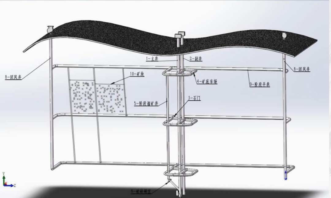
The shaft development method involves excavating a vertical shaft downward from the surface—typically with an inclination greater than 90° or nearly vertical—to establish the hoisting, transportation, ventilation, and drainage systems required for underground mine extraction. At its core, this method uses the shaft as the primary vertical passage connecting the surface to each mining stage, enabling the efficient vertical transport of personnel, equipment, ore, and waste rock. A typical system includes key structures such as the main shaft, auxiliary shaft, return air shaft, stage-level drifts, and stone gates. The main hoisting level integrates ore from all stages, which is then conveyed via chutes, crushed, and finally lifted to the surface by cage or skip systems, significantly enhancing overall transportation efficiency.
(II) Applicable Ore Deposit Geological Conditions
This method is applicable to two typical types of ore deposits: 1. Steeply inclined deposits (dip angle > 40°–45°), such as iron, copper, and lead-zinc ores found in metallic mines—where the ore bodies extend significantly vertically, allowing shafts to directly penetrate all mining stages and reducing the length of crosscuts.
2. Deeply Buried, Gently Inclined/Horizontal Deposits (dip angle <15° and burial depth >200m): For example, sedimentary coal or salt mines—using vertical shafts to shorten the vertical transportation distance, thereby avoiding the challenges of long uphill gradients associated with inclined shaft development.
II. Comparison and Selection Criteria for the Core Layout Scheme of the Shaft Development Method
(1) Downward Shaft Development Method – The Most Widely Used and Reliable Approach
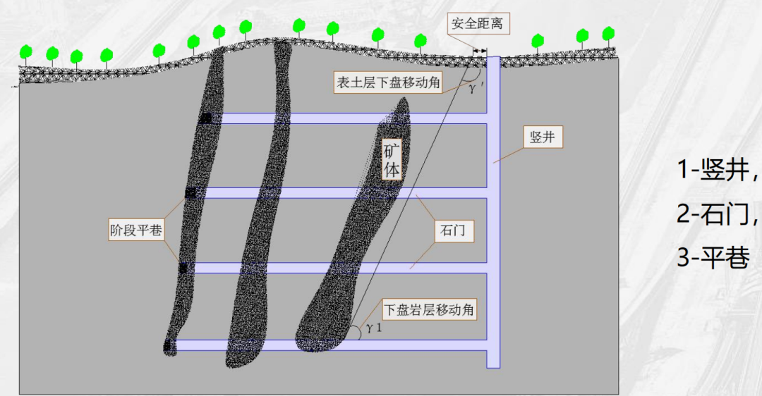
The down-dip shaft development method involves placing the main shaft in the surrounding rock outside the rock-movement zone beneath the orebody, and then excavating stage-by-stage bottom-level car sheds, crosscuts, and major transport drifts at each level, ultimately connecting to the orebody. From a technical perspective, this approach offers excellent shaft protection conditions and eliminates the need to leave safety pillars, which means ore resources can be recovered more efficiently, significantly reducing waste. Moreover, while the issue of increasing crosscut lengths with deeper mining is typically more pronounced in gently dipping orebodies, it becomes less significant—or even negligible—in cases where the orebody dips steeply (especially when the dip angle exceeds 70 degrees). In such scenarios, if the down-dip terrain, geological structures, and rock conditions are favorable for shaft excavation, the advantages of this method become even more evident.
Of course, this method also has certain limitations. When the dip angle of the ore body is relatively small, the length of the adit will increase significantly as the mining depth grows, which not only leads to a greater volume of excavation work and higher costs but also compromises transportation efficiency. For instance, in the extraction of some gently inclined ore bodies, the excessively long adits result in longer travel times and higher energy consumption for ore transport. Moreover, if the underlying geological conditions are complex—such as the presence of faults, fractured zones, or substantial water inflows—it can pose considerable challenges to both the construction and maintenance of vertical shafts.
In engineering applications, the sub-level shaft development method is currently the most widely used vertical shaft development approach. For instance, the central shaft system at the Gongchangling Iron Mine employs this very method. Given the steep dip angle of the mine’s orebody, this technique effectively protects the shaft structure, minimizes the need for safety pillars, and significantly boosts the recovery rate of ore. Meanwhile, through rational stage division and strategic layout of crosscuts, the method enables efficient multi-stage ore hoisting, providing a robust foundation for the mine’s sustained and stable production.
(II) Upper Shaft Development Method – A Targeted Solution for Special Topographic and Geological Conditions
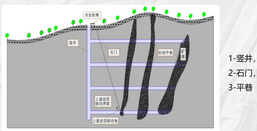
The upper-slope shaft development method involves positioning the main shaft outside the rock-movement zone of the upper slope, then excavating stage drifts from the shaft to reach the ore body. This method is typically used only in special circumstances. For instance, it may be considered when surface topography restricts the availability of suitable sites for industrial facilities on the lower slope or flanks, leaving the upper slope as the only viable option. Additionally, if transportation links—both internal and external to the mine—require that the concentrator and tailings storage facility be located exclusively on the upper-slope side of the ore body, constructing an upper-slope shaft becomes the most cost-effective solution, significantly reducing transportation expenses. Lastly, this approach is also chosen when the geological and hydrogeological conditions of the lower-slope rock layers are too complex to support shaft excavation.
However, the upper-pole shaft development method also faces several technical challenges. Since it requires excavating long-distance rock tunnels in the early stages, this leads to a significant increase in infrastructure investment and extends the construction period by 15% to 20%. Meanwhile, during the mining process, the surrounding rock of the upper ore body may shift due to extraction activities, placing higher demands on the protection of the shaft itself. As a result, enhanced support structure design is necessary to ensure the safety and stability of the shaft.
In practical applications, a certain lead-zinc mine serves as a prime example. Due to the open top-layer terrain and well-developed karst formations in the lower layer, it was impossible to excavate vertical shafts at their conventional locations. Ultimately, the mine adopted the upper-layer vertical-shaft development method, complemented by a chute system. Thanks to the chutes, ore can be transported automatically via gravity, significantly reducing transportation costs while boosting production efficiency.
(III) Wing Shaft Development Method – An Efficient Solution for Short-Strike Ore Bodies
The flank shaft development method involves placing the shaft on one side of the orebody trend, outside the rock movement zone along the orebody’s flanks, and then establishing development connections at each stage level—such as bottom-level car sheds, crosscuts, and stage-level transport drifts—linking these to the orebody itself. This method is particularly suitable for orebodies with short lengths and small dip angles. Additionally, it is employed when surface topography restricts layout options, and only the flank terrain provides favorable conditions for setting up the industrial site.
From a technical perspective, the advantage of the flank shaft development method lies in its ability to avoid the impact of complex geological conditions in the hanging and footwalls on shaft construction and operation, while also reducing the amount of drift work required. However, this method also has notable limitations. Since underground transportation is conducted in a single direction, the energy consumption for hauling becomes excessively high, leading to increased transportation costs and lower efficiency. Moreover, the mining face can only advance unidirectionally, which restricts both the excavation and extraction rates, thereby capping the mine's overall production capacity to some extent. In certain small-scale metal mines or vein-type ore bodies, where the ore deposits are relatively modest in size, adopting the flank shaft development method can fully leverage its key benefit—minimizing drift work. At the same time, by carefully designing efficient transport routes and utilizing trackless equipment, it’s possible to partially offset the method’s inherent drawback of low transportation efficiency.
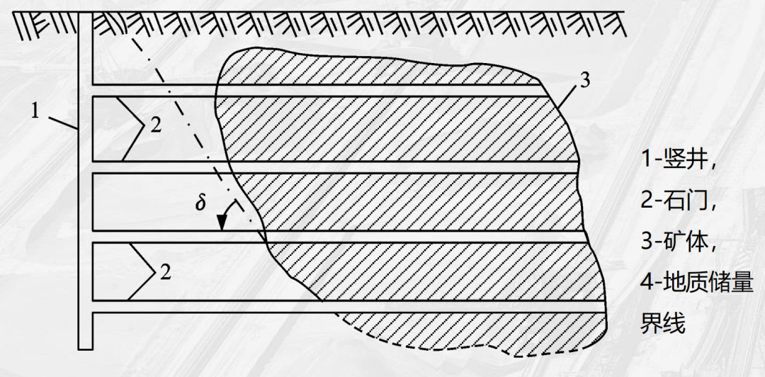
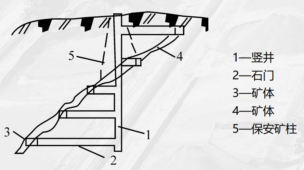
(IV) Special Scenarios: The Shaft Development Method Through Mineral Bodies
The shaft development method, which involves driving shafts through the ore body, is a relatively specialized approach. To ensure the stability of the shafts, it is essential to leave behind protective pillars, which inevitably leads to significant ore losses. Estimates suggest that the ore loss rate could range from 15% to 20%. As a result, this method is rarely applied in deposits of rare and precious metals. Generally speaking, it is only cautiously considered when the ore value is low, the ore body is thin (less than 5 meters), and the dip angle is below 15 degrees. In such cases, the ore loss caused by leaving protective pillars is relatively minimal, making the impact on overall economic efficiency acceptable.
III. Key Technologies for Engineering Optimization and Efficiency Enhancement in Shaft Development Methods
(1) Enhance System Optimization Design
- 1. Main Lift Level Setting : By setting up a mine bunker and crushing chamber in the middle of the shaft, the ore transportation process across all stages can be efficiently integrated. Take a large-scale metal mine as an example—by centrally conveying ore from each stage to the central bunker, and then using a combination of jaw crushers and cone crushers to reduce the ore size to ≤300mm, the material is subsequently hoisted to the surface via skip buckets (ideal for high-capacity operations, with lifting capacities ranging from 500 to 1,500 t/h) or cage systems (versatile, capable of handling both personnel and materials simultaneously). Compared to traditional multi-stage hoisting methods, this approach significantly reduces the number of hoisting devices and energy consumption, boosting overall efficiency by 30% to 40%.
- 2. Hybrid Well Technology : The shaft simultaneously accommodates both skip hoists (responsible for ore lifting) and cage systems (used for transporting personnel and materials), complemented by a counterweight system that significantly enhances lifting efficiency. According to statistics, mixed-shaft systems boost lifting efficiency by approximately 30% compared to single-cage shafts, making them particularly well-suited for large-scale mines with annual production exceeding 1 million tons. For instance, a major iron mine has adopted a mixed-shaft lifting system; through optimized selection of lifting equipment and precise adjustment of operational parameters, it has achieved an impressive annual ore-handling capacity of 1.5 million tons, while ensuring efficient and orderly transportation of both personnel and materials.
(II) Integration of Ventilation and Safety Systems
- 1. Ventilation System Optimization : The return air shaft, combined with the main and auxiliary shafts to form a continuous airflow, is crucial for maintaining high-quality air underground. By strategically positioning fan rooms—such as the high-power axial fans installed at the northwest return air shaft of the Gongchangling Iron Mine—airflow velocity can be effectively controlled within the range of 6–8 m/s, ensuring adequate ventilation for all working areas underground. This approach not only guarantees that underground air quality meets national standards but also helps minimize the risk of occupational health hazards.
- 2. Rock Movement Zone Monitoring : By combining surface displacement sensors with underground convergence meters for monitoring, it’s possible to continuously track the stability of surrounding rock around the shaft in real time. For instance, at a deep-mining operation, multiple displacement sensors were strategically placed around the shaft, transmitting data wirelessly back to the monitoring center. A pre-set warning threshold was established—cumulative displacement exceeding 50 mm or a rate surpassing 5 mm/day. Once the monitored data breaches these thresholds, the emergency response plan is immediately activated, effectively ensuring the safe operation of the shaft.
(III) Digital and Intelligent Upgrades
- 1. Automation Control Upgrade The shaft hoist is equipped with a PLC control system, enabling precise positioning of the cage (with an error margin of less than 10mm) and featuring self-diagnostic fault detection capabilities. When the system identifies abnormalities—such as cage overspeed or overwinding—it automatically activates the safety braking mechanism and promptly alerts maintenance personnel via the remote monitoring system. This proactive approach effectively reduces accident risks and significantly enhances the reliability of the hoisting system.
- 2. BIM Technology Application At critical areas such as the connection points between vertical shafts and stone gates, BIM technology can be applied to create 3D models that visually showcase the roadway's spatial structure. By simulating and analyzing stress distribution under various support schemes, we can optimize the support structures at roadway intersections—for instance, by adopting a combined approach of high-strength bolts and cable anchors—effectively reducing the risk of stress concentration, enhancing roadway stability, and ultimately lowering maintenance costs.
IV. Typical Engineering Cases and Selection Decision References
(1) Steeply Inclined Ore Body: A Model for Downward Shaft Development —— Gongchangling Iron Mine
As a prime example of the sublevel stoping method, the Gongchangling Iron Mine features ore bodies with an exceptionally steep dip angle of up to 75° and an average burial depth reaching 800 meters—typical characteristics of steeply inclined, deeply buried ore deposits. The mine employs a 6-meter-diameter sublevel shaft as its primary hoisting channel, complemented by stage drifts that are carefully controlled to span 50 to 80 meters in length. By installing ore chutes at each stage, the ore can swiftly descend by gravity directly into the main crushing chamber located at the hoisting level. After being crushed, the ore is efficiently lifted to the surface via large skip buckets, achieving an annual hoisting capacity of up to 3 million tons. This innovative layout significantly reduces ore transportation time across all stages—cutting it by 25% compared to conventional multi-level hoisting systems—thereby boosting overall production efficiency.
(2) Gently Inclined Deep Ore Deposits: Special Applications of Upper-Rock Shaft Systems — A Certain Lead-Zinc Mine
A certain lead-zinc mine features an ore body with a dip angle of only 12°, classifying it as a gently inclined deposit. Moreover, the lower wall of the ore body lies within a river protection zone, making it impossible to construct a vertical shaft. After a comprehensive assessment, the mine decided to build a vertical shaft on the upper wall, reaching a depth of up to 1,000 meters. Due to the shallow dip angle of the ore body, the length of each stage drift reached as much as 150 meters. To tackle the challenge of long-distance horizontal transportation, the mine implemented an innovative rail-less truck relay system, transporting ore from the mining face directly to a transfer station located near the vertical shaft—and then lifting the material to the surface via the shaft itself. This groundbreaking transportation method effectively overcame the difficulties associated with long-distance horizontal transport in gently inclined ore bodies, ensuring the mine’s efficient and uninterrupted production.
(III) Selection Decision Matrix
| Mineral deposit conditions | Lower shaft | Upper shaft well | Side-wing shaft |
|---|---|---|---|
| Angle of inclination > 70° | ★★★★☆ | ★★☆☆☆ | ★★★☆☆ |
| Tilt angle: 15°–45° | ★★★☆☆ | ★★☆☆☆ | ★★★★☆ (Short-Term Trend) |
| Industrial site restrictions | No special requirements | The upper platform requires flat terrain. | The flanks require separate venues. |
| Geological Complexity | The lower body needs to be stable. | The upper plate must be stable. | The flank needs fewer fractures. |
In practical engineering, the selection of the shaft development method requires a comprehensive consideration of multiple factors, including the ore body dip angle, industrial site conditions, and geological complexity. For instance, if the ore body dip angle exceeds 70°, a down-dip shaft is the preferred choice; however, when constrained by the industrial site layout, the appropriate shaft location must be determined based on the terrain.

Previous Page
