-
About Us
-
-
-
Contact Us

Method for Determining Rock Movement Zones and Its Application in Mining Engineering – Heijinggang Broadcast
01. Basic Concepts of Rock Movement
Defining the Collapse Zone and the Movement Zone
During the mining process, rock falls are a common occurrence, often causing significant impacts on the surface and creating two critically important zones: the collapse zone and the movement zone. When rockfall extends to the surface, the collapse zone (B) emerges—this is the area directly affected by the destruction, characterized by obvious signs of damage such as cracks and subsidence. The extent of the collapse zone is precisely defined by the collapse line (C/F), which acts as a clear boundary distinctly separating the collapse zone from surrounding areas.
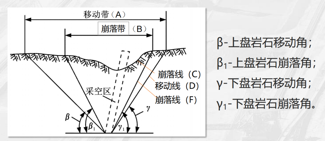
The moving zone (A), however, is different—it represents an area where deformation and displacement occur on the surface, though these changes are relatively subtle and typically do not result in obvious cracks or ruptures. The boundary of the moving zone is defined by the movement line (D), which marks the precise extent of surface deformation. Together, the collapse zone and the moving zone delineate the overall footprint of mining activities on the ground surface. Accurately defining these zones is critical for ensuring safe mine design and efficient production operations. During the mine planning phase, only by precisely identifying the boundaries of both the collapse zone and the moving zone can operators properly arrange various facilities, thereby preventing safety incidents and financial losses caused by rock movement.
Key angle parameter definitions
The hanging-wall movement angle (β) refers to the angle formed between the boundary line of rock movement in the hanging wall of a mineral deposit and the horizontal plane. This angle intuitively reflects the displacement trend of the surrounding rock in the hanging wall toward the mined-out area. Similarly, the footwall movement angle (γ) represents the angle between the boundary line of rock movement in the footwall and the horizontal plane, serving as a measure of the displacement tendency in the footwall’s surrounding rock. These angular parameters are not static—they are closely tied to the dip angle (α) of the ore body, with the magnitude of the ore-body dip directly influencing the values of both the hanging-wall and footwall movement angles. Additionally, the mechanical properties of the rock play a crucial role: rocks with different mechanical characteristics will exhibit significantly varying movement angles. For instance, hard rocks typically have smaller movement angles due to their strong resistance to deformation, whereas softer, more ductile rocks tend to display larger movement angles, making them more prone to displacement and deformation.
The upper-wall collapse angle (β₁) is the angle between the boundary line of the collapse zone and the horizontal plane. It is used to clearly define the dip degree of the area where the overlying rock directly collapses, making it crucial for determining the extent of the collapse zone. Similarly, the lower-wall collapse angle (γ₁) refers to the inclination angle that defines the collapse region of the underlying rock. Both of these collapse angles are closely linked to the ore body’s dip angle and the mechanical properties of the rock. In actual mining operations, accurately measuring and analyzing these collapse angles enables engineers to better predict the development trends of the collapse zone, allowing them to proactively implement appropriate protective measures and ensure the safe continuation of mining activities.
02. Method for Delineating the Range of Rock Movement
(1) Theoretical Calculation Methods
Probability Integral Method
The Probability Integral Method is a technique rooted in continuum mechanics theory, treating rock movement as a continuous deformation process. Under conditions of full-scale mining, this method employs a series of precise mathematical formulas to describe surface movements and deformations. Among these, horizontal and vertical deformation values serve as key indicators for determining the angle of movement; typically, horizontal deformation is capped at ≤3 mm/m, while vertical deformation is limited to ≤3 mm/m. Based on these criteria, the method solves for the movement angle using transcendental equations. Importantly, the formulas fully integrate several critical parameters, including mining depth (H), mining thickness (m), and subsidence coefficient (η). Mining depth directly influences the magnitude of stress experienced by the rock, whereas mining thickness determines the scale of rock movement. Meanwhile, the subsidence coefficient reflects the specific characteristics of rock settlement. By comprehensively considering these parameters, the method accurately calculates the movement boundaries in both the strike and dip directions, providing a robust theoretical foundation for defining the extent of rock displacement.
Engineering Analogy Method
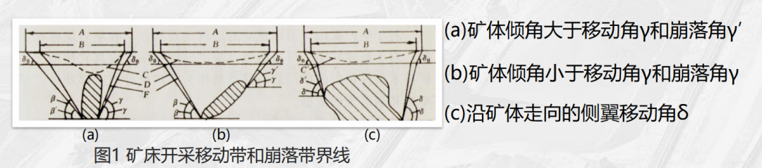
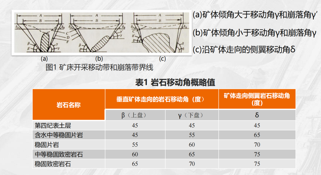
The engineering analogy method is an experience-based approach that relies on extensive accumulation of real-world engineering cases and data. In the "Table of Approximate Values for Rock Movement Angles" (Table 1), typical reference values for movement angles are provided for various rock types, such as stable schists and dense rocks. For Quaternary topsoil layers, the movement angles for the hanging wall, footwall, and sidewalls are all set at 45°. In contrast, for stable, dense rocks, the movement angle of the hanging wall is 65°, while the footwall angle is 70°, and the sidewall angle reaches 75°. In practical applications, it is essential to conduct a detailed analysis by considering the relationship between the ore body dip angle (α) and the movement angle. Specifically: when α > γ/γ₁, the extent of footwall movement is primarily governed by the ore body dip angle, making the stability of the footwall slope critical—thus requiring more frequent monitoring. On the other hand, when α < γ/γ₁, the hanging wall movement boundary extends farther toward the surface, necessitating enhanced protection of structures and facilities located in the hanging wall area. Meanwhile, the sidewall movement angle (δ) along the strike direction controls the influence zones at both ends of the ore body, helping to prevent interference between adjacent mining areas and ensuring the safe and orderly progression of the entire mine operation.
(II) Measured and Numerical Simulation Techniques
Surface Deformation Monitoring Method
The ground deformation monitoring method is a direct approach for acquiring information on rock movement. By carefully establishing leveling networks and GPS displacement monitoring points on the mine surface, it enables real-time, accurate measurement of both vertical subsidence (in mm) and horizontal displacement (in mm/m). These data serve as intuitive indicators of rock movement, and their analysis helps reveal the underlying deformation trends across the surface. Combined with criteria such as curvature radius (≥15,000 m) and horizontal deformation thresholds, this method allows for the dynamic adjustment of the boundaries defining the active movement zone. If horizontal displacement in a particular area exceeds the preset threshold, or if the curvature radius falls below the standard value, the boundaries of that area’s movement zone must be reassessed and adjusted promptly—ensuring precise identification of the extent of rock movement.
Three-dimensional numerical simulation
Three-dimensional numerical simulation technology leverages advanced software tools such as FLAC3D and 3DMine to construct coupled models of ore bodies and surrounding rock masses. During the modeling process, it is essential to accurately input rock physical parameters—such as elastic modulus and Poisson’s ratio—that determine the mechanical properties of the rock. Additionally, mining process parameters—including segment height and caving step distance—also significantly influence the simulation results. By simulating the evolution of stress distribution and displacement fields within the mined-out areas, the process can generate visualized, three-dimensional models of the resulting movement zones. For complex ore bodies, especially those containing multiple parallel veins, these 3D models provide precise delineation guidelines, enabling engineers to gain a comprehensive understanding of the three-dimensional spatial characteristics of rock movement. This, in turn, helps them develop more scientifically sound and rational mining plans, as well as implement effective safety measures.
03. Key Influencing Factors and Engineering Countermeasures
(1) The Decisive Role of Rock Properties
The properties of rock play a critical and decisive role in determining the extent of rock movement, with rock stability being a key factor influencing the selection of the movement angle. Rocks of varying degrees of stability exhibit significantly different movement angles. For instance, in moderately stable schists compared to highly stable, dense rocks, the upper-block movement angle (β) for the former typically ranges around 55°, while the latter can reach as high as 65°. Although this difference may seem minor—only about 10°—it can have a substantial impact in real-world engineering applications. According to basic geometric calculations, under otherwise identical conditions, a 10° discrepancy in the movement angle can lead to an increase of roughly 15% in the area affected on the ground surface. This underscores the importance of accurately assessing rock stability during the mine design phase. If the stability of the rock is misjudged—if an inappropriate, rough estimate of the movement angle is adopted—the seemingly safe areas could inadvertently fall within the zone influenced by rock movement, potentially triggering a cascade of safety risks. These risks might include cracks or collapses in surface structures, as well as deformation or even collapse of underground roadways. Therefore, in practical engineering projects, it is essential to place utmost emphasis on the influence of rock properties. Conducting thorough, on-site rock mechanics tests should be prioritized to obtain precise rock mechanical parameters. Only with these accurate data can engineers confidently determine the appropriate movement angle, thereby ensuring both the safety and stability of mine operations.
(II) The Coupling Effect Between Ore Body Dip Angle and Mining Depth
Pitch angle influence
The dip angle (α) of ore bodies significantly influences the extent of rock movement. When the ore body is steeply inclined—specifically, when α > 60°—the hanging-wall rock mass tends to slide along bedding planes under the combined effects of gravity and mining-induced stresses. This sliding motion can dramatically expand the range of rock displacement. Therefore, in such cases, it is essential to appropriately increase the hanging-wall movement angle by 2° to 5° to accurately delineate the boundaries of rock movement. For instance, at a certain mine extracting steeply inclined ore bodies, initial designs were based on conventional movement angles. However, during the mining process, noticeable cracks and deformations appeared on the surface of the hanging wall. After a thorough reassessment and adjustment of the hanging-wall movement angle, the impact of rock movement was effectively contained. On the other hand, for gently inclined ore bodies—where α < 30°—the movement range of the footwall rock mass is relatively small. This is because the mining-induced stresses acting on the footwall rock are comparatively minimal, resulting in an inconspicuous tendency for movement. Leveraging this characteristic, mine planners can strategically position and orient footwall development roadways to fully capitalize on the limited movement potential of the footwall, thereby reducing roadway maintenance costs and enhancing overall mining efficiency.
Depth Effect
As the mining depth (H) increases, the range of rock movement also changes. When the mining depth exceeds 500 meters (H > 500m), in-situ stresses significantly rise. This increase in in-situ stress alters the mechanical properties of the rock, causing the rock’s movement angle to expand by 3° to 8°. This phenomenon occurs because, during deep-mining operations, rocks are subjected to greater overburden pressure and tectonic stresses, thereby increasing their likelihood of deformation and failure. To address this situation, it is essential to strengthen ground-pressure monitoring in deep-mining areas. By installing advanced ground-pressure monitoring systems, operators can continuously track changes in in-situ stress and promptly adjust mining plans and support measures accordingly. Additionally, reinforcing support systems in deep-mining zones is equally critical. Employing high-strength support materials and adopting rational support structures—such as combined anchor-cable and anchor-bar systems—can effectively enhance the stability of surrounding rock masses, mitigating safety risks caused by rock movement and preventing potential accidents.
(III) Adaptive Adjustment of Mining Methods
Different mining methods have varying impacts on the extent of rock movement, so adaptive adjustments must be made according to the specific characteristics of each method. When using the room-and-pillar method, since the mined-out areas rely on pillars to support the roof, it is essential to leave behind safety pillars based on the expected movement angles. The size and location of these safety pillars must be precisely calculated to ensure they can effectively withstand the pressure from the overlying rock layers, thereby preventing collapse in the mined-out zones and mitigating the potential impact of rock movement on surrounding areas. For instance, at one mine employing the room-and-pillar method, insufficient safety pillars were left behind, leading to localized collapses in the mined-out areas. This, in turn, triggered widespread rock movement, severely damaging nearby tunnels and equipment. In contrast, the caving method leverages the natural fracturing behavior of rocks by defining safety boundaries based on the caving angle. Under this approach, it’s crucial to thoroughly consider the rock’s caving properties as well as the geological conditions of the orebody, carefully determining the optimal caving step distance and sequence to control both the extent and pace of rock caving, thus ensuring safe and efficient mining operations.
For the stowing method of mining, since the backfill material can provide substantial support to the surrounding rock, effectively controlling its displacement, the extent of the movement zone can be appropriately reduced. However, when adopting the stowing method, it is crucial not to blindly shrink the movement zone; instead, the coupling relationship between the backfill strength and rock movement must first be verified. Through laboratory tests and numerical simulations, researchers can investigate the deformation and failure patterns of the backfill under various stress conditions, as well as its impact on rock movement. Only after confirming that the backfill can adequately support the surrounding rock without being compromised by rock movement itself should the movement zone be reasonably minimized—thereby enhancing the recovery rate of mineral resources.
04. Engineering Applications and Safety Design
- Security Mine Pillar Delineation Principles
In mine exploitation, defining the safety pillar is crucial. Its width (W) is calculated using a rigorous formula: W = H × cotβ - Mineral body thickness (d) / sinα. This formula takes into account key factors such as mining depth (H), the overlying strata movement angle (β), as well as the mineral body thickness (d) and dip angle (α). At a particular mine, with a mining depth of 300 meters, an overlying strata movement angle of 60°, a mineral body thickness of 5 meters, and a dip angle of 45°, the calculated safety pillar width comes out to approximately 120 meters. For critical facilities like shafts, tunnels, and industrial sites, ensuring their safety requires positioning them at least 20 meters outside the movement zone—especially for Class I protected structures. This precaution is essential because, during actual mining operations, rock movements can severely damage these facilities, potentially leading to issues such as shaft collapses or ground cracks in industrial areas. Such disruptions not only jeopardize normal mining operations but also pose significant risks to both equipment and personnel safety.
As mining progresses, the mechanical properties of the rock and the stress distribution will change, necessitating timely updates to the abutment angle data. At an early stage of mining, a certain mine determined the abutment angle for the hanging wall to be 60° based on rock characteristics and accumulated experience. However, as mining depth increased and the rock became more fractured, the abutment angle was subsequently re-measured at 65°. Based on this updated value, the safety pillars were redefined accordingly. For deep-seated ore bodies, considering the variability of in-situ stresses and the softening of the rock, adopting a variable-angle approach to delineate the safety pillars can more accurately determine their boundaries. For instance, using β = 60° in the upper section and β = 65° in the lower section not only ensures safe extraction in the upper levels but also minimizes ore loss from deeper zones, thereby enhancing resource recovery efficiency.
- Tunnel Development and Layout Strategy
In the vertical layout of development roadways, the dip angle of the lower wall (γ) is typically greater than that of the upper wall (β). This characteristic gives a clear advantage to placing the main shaft on the lower wall. Because the dip angle of the lower wall is larger, positioning the main shaft there can shorten the length of the crosscut, thereby reducing both the volume and cost of development work. For instance, in a certain metal mine, when the main shaft was located on the lower wall, the crosscut length was reduced by about 30% compared to when it was placed on the upper wall, significantly boosting mining efficiency. However, if the terrain of the upper wall happens to be more favorable—such as being closer to transportation routes, water sources, or other key facilities—it may still be considered to position the main shaft on the upper wall. In such cases, though, it is essential to rigorously verify the safety distance between the upper-wall movement boundary and the roadway, ensuring that this distance remains no less than 15 meters (Level-2 protection). This precaution is critical to prevent rock movements from the upper wall from damaging the roadway, thereby safeguarding the stability and safe operation of the mine infrastructure.
When positioning development roadways along the ore body trend, using the midpoint of the ore volume as the optimal location is a fundamental principle. This is because placing the roadway at the ore volume’s midpoint minimizes transportation work (t·km) on both sides, thereby reducing transportation costs and energy consumption. For regular ore bodies, the midpoint typically corresponds to half the length of the ore body’s strike; however, for more complex ore bodies, the center of gravity can be determined using a segmented weighted approach. In mines with multiple ore bodies, calculating the ore volume midpoint via the segmented weighted method and positioning the development roadway there effectively cuts down on energy consumption and equipment wear during transportation. It’s crucial to avoid locating the roadway in areas where stress is concentrated unilaterally, as this could lead to roadway deformation and compromise normal operations. If the roadway is situated in a region of unilateral stress concentration, the surrounding wall may endure excessive pressure, potentially resulting in cracks, collapses, and other safety hazards.
(III) Classification of Surface Facility Safety Levels
| Protection Level | Facility Type | Mobile Out-of-Band Safety Distance | Protective measures |
| Level One | Main shaft, substations | ≥20m | Reinforced concrete support + displacement monitoring system |
| Level Two | Ventilation shaft, filling shaft | ≥15m | Flexible Support + Regular Slope Stability Analysis |
| Level Three | Temporary storage yard, temporary access road | ≥10m | Warning signs + Seasonal settlement monitoring |
The main shaft serves as the critical passage for lifting ore, personnel, and equipment in a mine; once damaged, it can severely disrupt normal mining operations. Employing reinforced concrete support structures helps strengthen the shaft’s overall integrity, enabling it to withstand the pressure caused by rock movement. Meanwhile, a displacement monitoring system allows real-time tracking of any shifts in the shaft’s position, promptly identifying potential safety hazards. The ventilation shaft is primarily used for air circulation underground, ensuring proper airflow to maintain a safe working environment. Its reliable operation is essential for protecting the lives of miners working below ground. Flexible support systems are designed to accommodate moderate rock deformation, minimizing damage to the shaft structure. Additionally, regular slope stability analyses help detect early signs of potential sliding or collapse, allowing timely implementation of reinforcement measures. Although temporary stockpiles and access roads are relatively secondary components, they still require appropriate protective measures. Warning signs can alert workers to stay clear of hazardous areas, while seasonal settlement monitoring ensures that any ground subsidence caused by rock movement is promptly identified, enabling swift corrective actions to maintain the safe use of these facilities. By clearly defining safety levels and implementing tailored protective measures, we can effectively safeguard surface infrastructure and significantly reduce safety risks during mining operations.
05. Summary
Defining the range of rock movement is a core step in mining engineering, crucial for ensuring safety and enhancing economic efficiency. This process spans across a wide range of disciplines and is influenced by numerous factors. From a theoretical perspective, accurately understanding the boundaries between the caving zone and the movement zone—and clearly defining key angular parameters—is the foundation for all subsequent work. In terms of methodology, theoretical calculation approaches such as the probability integral method and the engineering analogy method each offer distinct advantages and are suited to specific scenarios, providing essential tools for the initial determination of rock movement ranges. Meanwhile, field measurement and numerical simulation techniques—through methods like surface deformation monitoring and 3D numerical modeling—enable dynamic tracking and precise prediction of rock movement zones.
When it comes to key influencing factors, rock properties, ore body dip angle, mining depth, and mining methods all significantly impact the extent of rock movement. Rock properties determine the value of the movement angle, while the combined effects of ore body dip and mining depth influence both the direction and range of rock displacement. Meanwhile, the choice of mining method must be adaptively adjusted according to actual site conditions to effectively control rock movement. In engineering applications, tasks such as defining safe mine pillars, planning development roadways, and categorizing surface facilities based on safety levels are all closely tied to the predicted range of rock movement—aiming to ensure both the safety and efficiency of mine operations.