-
About Us
-
-
-
Contact Us

An article to understand medium and deep hole ore drawing — Black Diamond Report
Preface
In the mining field, the selection and application of ore drawing technology have a crucial impact on mining efficiency, cost, and safety. Medium and deep hole ore drawing technology, with its unique advantages such as higher production efficiency, relatively reasonable cost input, and a wide range of applicability, holds an important position in modern mining operations. With the continuous development of mining engineering and ongoing technological advancements, medium and deep hole ore drawing technology is also being continuously optimized and improved. In-depth research and understanding of it help to further enhance the overall level of mining operations and achieve efficient and safe resource extraction. This article will provide a detailed explanation of the relevant content of medium and deep hole ore drawing technology.
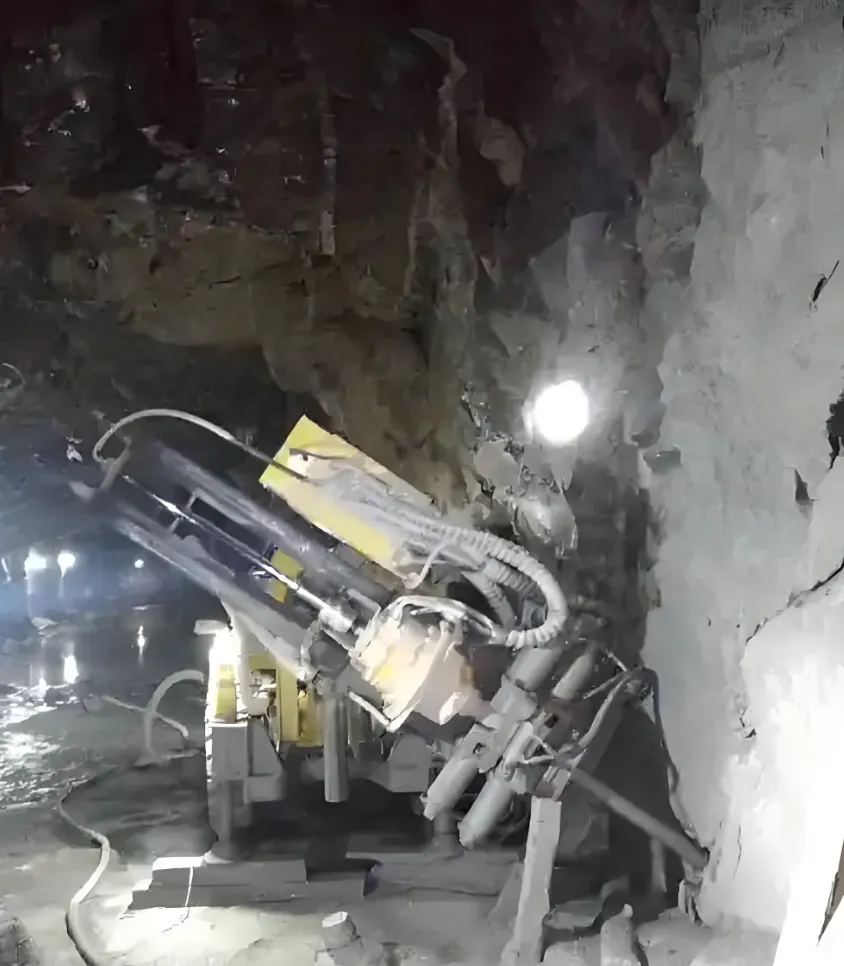
I. Basic Parameters of Medium and Deep Hole Ore Drawing
(1) Borehole Diameter and Depth
Medium and deep holes in mining operations have clear standards for borehole diameter and depth. The diameter range is usually between 50 - 70mm, and the depth should not exceed 15m. These parameters are not set arbitrarily but are based on comprehensive considerations. From the perspective of mining efficiency, appropriate borehole diameter and depth ensure efficient drilling operations and reduce unnecessary time waste. If the diameter is too small, charging becomes difficult, and the explosive energy cannot be effectively transmitted, resulting in poor ore fragmentation; if the diameter is too large, it may cause excessive wear on drilling equipment, increase maintenance costs, and significantly affect the stability of the rock mass. Regarding depth, overly deep blast holes exponentially increase drilling difficulty and may cause borehole deviation, affecting blasting effectiveness; overly shallow holes cannot fully utilize the advantages of medium and deep hole ore drawing, reducing mining efficiency. In practice, a certain mine initially tried increasing the hole depth to 20m during medium and deep hole ore drawing operations, but found that drilling speed significantly decreased and the proportion of large ore blocks after blasting increased markedly, greatly increasing the workload of secondary crushing and seriously affecting overall mining progress and costs. Therefore, strictly adhering to the diameter of 50 - 70mm and a depth not exceeding 15m is crucial for ensuring mining efficiency and reducing costs.
From a safety perspective, reasonable borehole diameter and depth can reduce blasting risks. During blasting, the parameters of the blast holes directly affect the distribution of explosives and the release of explosive energy. If the diameter and depth are unreasonable, explosive energy may concentrate in local areas, causing excessive rock fragmentation and scattering, posing serious threats to personnel and equipment. For example, when the diameter is too large and the depth too deep, the shock force generated by the explosive detonation may exceed the rock's bearing capacity, causing rock collapse and roof fall accidents. Therefore, to ensure the safe conduct of mining operations, the borehole diameter and depth parameters of medium and deep holes must be strictly controlled.
(2) Blast Hole Arrangement Methods
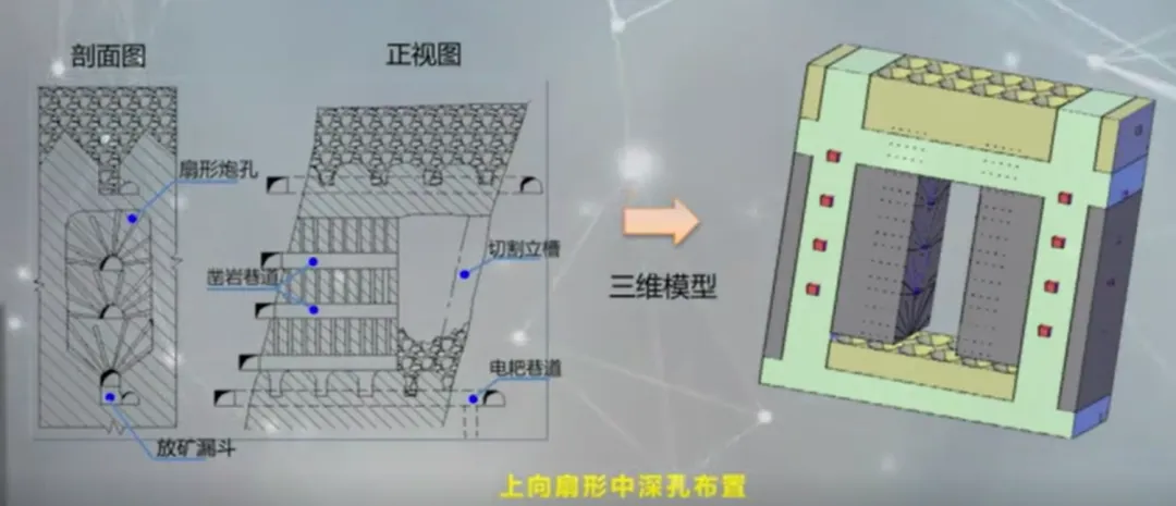
There are mainly two blast hole arrangement methods: parallel holes and fan-shaped holes. Fan-shaped holes can be further divided into horizontal fan-shaped and upward fan-shaped. Each arrangement method has its applicable scenarios and advantages and disadvantages.
The parallel hole arrangement method features blast holes parallel to each other, with equal spacing along the entire length of the holes. This arrangement is suitable for ore bodies that are regular in shape and have relatively uniform ore properties. Its advantage lies in the relatively uniform size of the collapsed ore blocks, which facilitates subsequent ore transportation and processing. In some mines with stable ore body thickness and consistent ore hardness, using parallel hole arrangement can result in a more concentrated particle size distribution of blasted ore, making subsequent screening and processing easier. However, parallel hole arrangement also has certain limitations. Due to its poor adaptability to ore bodies, when the ore body shape is irregular or there are faults and other geological structures, parallel hole arrangement may not fully function, leading to increased ore loss and dilution rates. Moreover, parallel hole arrangement requires more drilling tunnel excavation and more frequent equipment movement, which to some extent increases mining costs and operation time.
The fan-shaped hole arrangement method is highly flexible, especially effective when dealing with irregular ore bodies. In the same face, deep holes are arranged radially, with hole spacing gradually increasing from the collar to the bottom, dense at the collar and sparse at the bottom. Horizontal fan-shaped holes are mostly nearly horizontal with an upward inclination of 3 - 5°, commonly used for top and bottom pillar ore drawing; upward fan-shaped holes are widely used and play an important role in inter-pillar ore drawing and other operations. The advantages of fan-shaped hole arrangement are prominent: fewer equipment movements, moving only after completing a row, greatly improving operational efficiency; highly flexible for irregular ore bodies, allowing adjustment according to the actual shape of the ore body, effectively reducing ore loss and dilution; less drilling tunnel excavation, shorter preparation time, concentrated charging and blasting operations, saving time, good working conditions in tunnels, and relatively safe. In mining operations of a complex ore body, fan-shaped hole arrangement successfully adapted to the ore body's variable shape and improved ore recovery rate. However, fan-shaped hole arrangement is not without flaws: the size of blasted ore blocks is uneven, prone to producing large ore blocks, increasing secondary crushing workload and costs; and the utilization rate of deep holes is relatively low, possibly causing some resource waste.
II. Detailed Explanation of Blast Hole Arrangement Methods
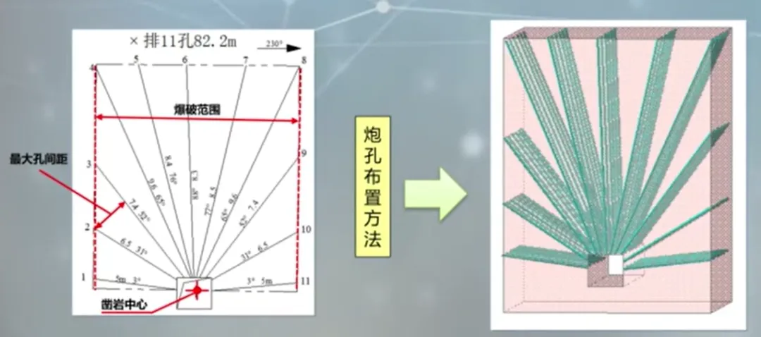
(1) Radial Arrangement Principle
In medium and deep hole ore drawing operations, blast hole arrangement follows a rigorous radial arrangement principle. Specifically, within the designed blasting range, the drilling center determined in the drilling tunnel is taken as the starting point for radial arrangement. Corner holes are arranged first because they play a key role in controlling the blasting range and contour. By reasonably arranging corner holes, the blasted ore boundary can meet mining requirements, reducing ore loss and dilution. In a mining example, insufficient attention to corner hole arrangement initially led to uneven ore boundaries after blasting, with some ore not effectively recovered, causing resource waste. Subsequently, the mine optimized the corner hole arrangement plan, strictly following the radial arrangement principle, significantly improving ore recovery rate. After arranging corner holes, the remaining blast holes are evenly added according to the selected maximum hole spacing. This arrangement ensures relatively uniform distribution of explosives within the ore body, making the ore subjected to uniform force during blasting, achieving good fragmentation. Evenly adding blast holes also avoids problems caused by unreasonable hole spacing, such as concentrated or unevenly dispersed blasting energy, reducing the generation of large ore blocks and improving mining efficiency.
(2) Key Points of Blast Hole Arrangement in the Same Row
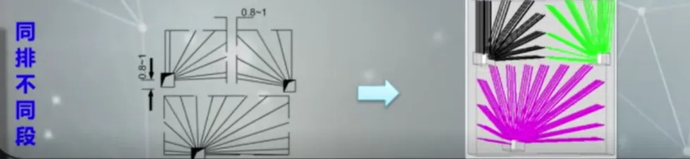
The key points of the arrangement of blast holes in the same row mainly manifest in two situations: the same row and same section, and the same row but different sections. For two drilling drifts blasted in the same row and same section, it is crucial to ensure an even distribution of blast holes. An even distribution of blast holes guarantees that the blasting energy is released uniformly within the ore body, thereby reducing the production rate of large blocks. In actual mining operations, a certain mine optimized the arrangement of blast holes in the same row and same section, making the distribution more uniform. The production rate of large ore blocks decreased from the original 30% to 15%, greatly reducing the workload of secondary crushing and improving the efficiency of ore transportation and processing. This is because evenly distributed blast holes allow the stress waves generated by the explosive detonation to propagate uniformly within the ore body, avoiding local over-fracturing and the formation of large ore blocks caused by stress concentration.
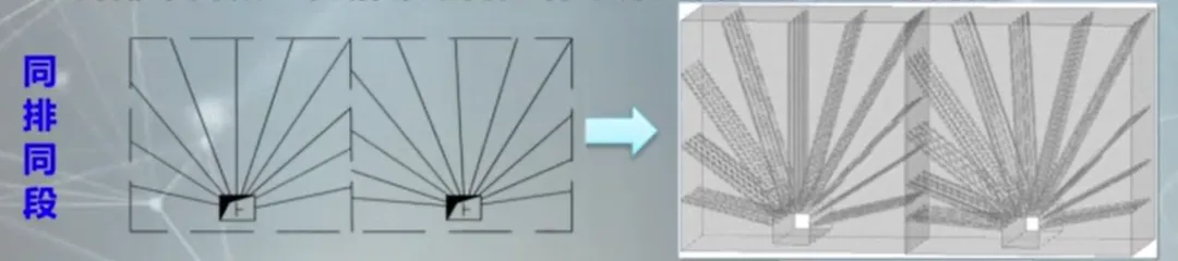
For the arrangement of blast holes in the same row but different sections, leaving a 0.8 - 1m gap at the boundary between adjacent blast holes is of great significance. This gap effectively prevents interference between adjacent blast holes during blasting. When blast holes are detonated simultaneously, without this gap, the explosion stress waves between adjacent blast holes may superimpose, causing locally excessive energy, over-fracturing of the ore, and producing a large amount of fines and flyrock. This not only affects ore quality but also poses safety risks to personnel and equipment. The gap also provides space for the movement of blasted rock, allowing the rock to break and move in the expected direction and manner, which helps control the blasting effect and reduces damage to the surrounding rock mass.
(3) Key Points for the Arrangement of Blast Holes in Different Rows
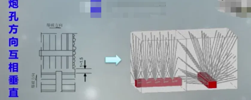
The key points for the arrangement of blast holes in different rows and different sections should not be overlooked. The directions of the blast holes should be perpendicular to each other to ensure that the blasting energy acts evenly on the ore in different directions, improving the blasting effect. For blast holes on the same plane, if the blasting directions are perpendicular, a gap of 1 - 1.5m should be left between them. This is because blast holes with perpendicular blasting directions generate intersecting stress waves during blasting. Without sufficient spacing, the interaction of stress waves may cause local areas to have overly concentrated or unevenly distributed energy, resulting in irregular fragmentation and an increase in the number of large ore blocks. In mining operations under complex geological conditions, neglecting the spacing requirements between blast holes in different rows led to a large block rate of up to 40% after blasting, seriously affecting mining efficiency and economic benefits.
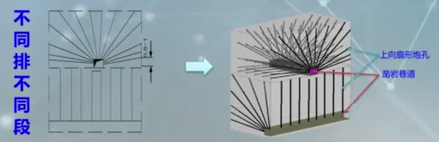
Wherever there is a spacing zone, an additional row of reinforcement blast holes should be added nearby. This is to eliminate blasting dead zones that may be caused by the spacing zone and ensure that the ore in the entire blasting area is fully fragmented. Reinforcement blast holes can supplement the blasting energy in the spacing zone, allowing the ore in that area to break as expected, thereby improving the overall blasting quality and reducing ore loss and dilution. By reasonably setting the arrangement parameters of blast holes in different rows, the effect of medium and deep hole ore drawing can be effectively improved, achieving efficient and safe mining operations.
3. Equipment and Charging for Medium and Deep Hole Ore Drawing
(1) Drilling Equipment
In medium and deep hole ore drawing operations, the choice of drilling equipment is crucial, as different drilling equipment has its own unique characteristics and advantages.
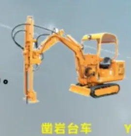
Atlas Copco's medium and deep hole drilling jumbos are highly favored for their advanced technology and excellent performance. For example, the Simba series of medium and deep hole drilling jumbos includes multiple models to meet different mining needs. The Simba S7 is suitable for medium and small-sized drifts for medium and deep hole drilling. It is equipped with a high-performance top hammer drill and a boom-type drilling mechanism, using the top hammer drilling method. The drilling diameter ranges from 51 to 89 millimeters. The BUT 32PD drill boom has a maximum extension of 1250mm and can drill ring blast hole groups and parallel holes with a maximum spacing of 5.9 meters, either upward or downward. The rod magazine can hold 10 + 1 drill rods, and the drilling depth can reach up to 20 meters. In the mining of a certain medium and small mine, the Simba S7, with its flexible boom-type drilling mechanism, can quickly and accurately perform drilling operations in complex drift environments, greatly improving drilling efficiency and shortening the mining cycle.
Sandvik's drilling jumbos also perform excellently. Taking the DL421 as an example, it is a compact, technologically advanced fully computerized deep hole jumbo with a variety of reliable automated functions, suitable for underground mine deep hole drilling, applicable to drifts with dimensions of 3.6×3.6 meters or larger. The jumbo can drill blast holes of 64 - 115 millimeters in diameter, with a maximum depth of 54 meters. It is designed for drilling vertical and inclined ring holes and fan-shaped holes on faces, parallel deep holes, and single deep holes, with optimal drilling accuracy. The entire drilling unit is mounted on a frame-type support connected to the front end of the chassis but relatively independent, making strip-shaped contact with the ground, providing a large and stable support area. Because the support frame is relatively independent, the drilling unit absorbs the vibration and torque of the drill itself, minimizing the impact on the chassis, which is especially beneficial for downward deep hole drilling. In the mining project of Macheng Iron Mine, the Sandvik DL421 medium and deep hole jumbo was successfully delivered and put into use. Its automation functions not only improved drilling accuracy but also reduced the risk of manual operation, providing strong support for efficient mining.

In addition to drilling jumbos, pneumatic drills are also widely used in medium and deep hole ore drawing. Models such as YG-40, YG-80, YG-90, and YGZ-90 each have their own characteristics. The YG-40 is equipped with a column support, suitable for hole depths less than 10 meters, with low power and mechanization level. However, it features a small size and flexible operation, allowing it to perform drilling tasks in some relatively narrow mining areas, completing drilling operations in special positions.
The YG-80 is a heavy-duty rail-type drill generally used with a jumbo, such as on the CZZ-700 single-machine drilling jumbo, where it can exert its powerful drilling capability. It has high impact energy and torque, suitable for drilling in medium-hard and harder rock, capable of completing drilling tasks quickly and efficiently. In the mining operations of a certain mine, facing hard rock, the YG-80 drill, assisted by the supporting jumbo, demonstrated strong rock-breaking ability, successfully completing a large amount of drilling work and laying a foundation for subsequent mining operations.
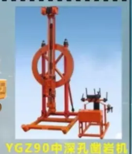
The YGZ - 90 type rock drill adopts a valve-less air distribution mechanism, featuring a simple structure, fewer parts, and easy maintenance. It fully utilizes the expansion work of compressed air, has low air consumption, flexible reversing, and stable and reliable operation. In practical applications, its low air consumption can reduce mining costs, while its stable and reliable performance ensures the continuity and efficiency of drilling operations, making it popular among many mining enterprises. The reasonable selection and application of these drilling devices can effectively improve the efficiency and quality of medium and deep hole ore drawing.
(2) Charging Equipment
Charging equipment plays a key role in medium and deep hole ore drawing, with different types of chargers suitable for different charging scenarios.
The FZY - 10 type charger is equipped with a manual stirrer, which gives it a significant advantage when charging explosives with high moisture content. In some mining operations, due to the high moisture content of the ore, explosives tend to become damp and clump, affecting blasting effectiveness. The manual stirrer of the FZY - 10 type charger can fully stir the explosives, ensuring even dispersion and maintaining the performance and blasting effect of the explosives. This charger has a charging capacity of 600kg/h, meeting the needs of certain scale mining operations, improving charging efficiency, reducing charging time, and thus accelerating mining progress.
The AYZ - 150 type charger has no stirrer and is mainly used for charging large-diameter holes. In charging operations for large-diameter blast holes, excessive stirring of explosives is not required. The AYZ - 150 type charger, with its structural characteristics, can quickly and accurately load explosives into the blast holes. In medium and deep hole ore drawing operations at a large mine, where many large-diameter blast holes need charging, the AYZ - 150 type charger plays an important role. Its efficient charging capacity and good adaptability to large-diameter holes ensure the smooth progress of charging work and provide a guarantee for subsequent blasting operations.
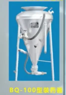
The application of these chargers not only increases the charging density, making the explosives more evenly distributed in the blast holes, thereby enhancing the blasting effect; it also improves the utilization rate of the blast holes. Even if the blast holes are deformed, as long as the charging pipe can be inserted, charging can be performed, reducing difficulties and explosive waste caused by hole problems. The use of chargers greatly reduces workers' labor intensity and improves the working environment. However, chargers also have some drawbacks, such as a high dust return rate, strict requirements on explosive moisture content, and the generation of static electricity during charging, which can reach 10,000 to 20,000 volts. To solve the static electricity problem, semiconductor charging pipes are usually used, and the charger is grounded. After compressed air charging is completed, explosive packages (electric detonators) are loaded. Nowadays, detonating cords and safety fuses are mostly used for initiation, increasing safety.
4. The Problem of Large Blocks in Medium and Deep Hole Ore Drawing and Solutions
(1) Analysis of Causes of Large Blocks
The generation of large ore blocks during medium and deep hole ore drawing is a common and troublesome problem with complex causes involving multiple factors.
Fan-shaped hole layout is one of the important causes of large block generation. When using fan-shaped hole layout, the distribution of explosives within the ore body is uneven. From the blasting principle perspective, the energy generated by the explosive blast needs to act evenly on the ore to fully break it. However, the characteristics of fan-shaped hole layout cause differences in explosive energy density between the hole mouth and the hole bottom. The explosives near the hole mouth are relatively concentrated with higher energy density, while the explosives at the hole bottom have relatively weaker energy. This uneven energy distribution leads to inconsistent ore fragmentation, easily producing large blocks. In medium and deep hole ore drawing operations at a certain mine, after blasting with fan-shaped hole layout, analysis of ore block size showed that the number of large ore blocks near the hole mouth area was significantly higher than in other areas, fully demonstrating the impact of fan-shaped hole layout on large block generation.
High explosive energy density at the hole mouth and inter-hole breakthrough are also key factors in producing large blocks. When the explosive energy at the hole mouth is too high, at the moment of blasting, the ore near the hole mouth is subjected to excessive impact force, causing local over-fragmentation and forming some smaller fragments. These fragments, when flying outward, may collide with surrounding ore that has not been fully broken, interfering with the normal fragmentation of the ore and resulting in large blocks. The occurrence of inter-hole breakthrough causes the explosive energy to be released prematurely between holes, failing to effectively act on the entire ore area, leading to some ore not being fully broken and thus forming large blocks. In actual blasting operations, large ore blocks are often observed at the locations of inter-hole breakthrough, which is direct evidence of this cause.
Excessive bottom spacing also causes large block problems. Bottom spacing is an important parameter affecting blasting effect, determining the distribution density of explosives within the ore body. When the bottom spacing is too large, the distance between explosives increases, and the stress waves generated by the explosion cannot effectively superimpose during propagation, resulting in insufficient blasting force on the ore and incomplete fragmentation. In the mining process of a certain mine, due to initially designed excessive bottom spacing, the large block rate of ore after blasting reached 40%, seriously affecting subsequent ore extraction efficiency and economic benefits.
Poor drilling accuracy is also a factor that cannot be ignored. In medium and deep hole drilling operations, if the angle deviation of blast holes reaches 1-2°, seemingly small deviations can significantly affect blasting results. Angle deviation causes the actual distribution of explosives within the ore body to differ from the design expectation, preventing blasting energy from accurately acting on the intended ore area. Depth deviation of blast holes also affects the burial depth of explosives, thereby influencing the release of explosive energy and ore fragmentation effect. In a certain mine's medium and deep hole operations, due to large angle deviations in some blast holes, a large amount of large ore blocks appeared after blasting, requiring secondary fragmentation, increasing production costs and operation time.
(2) Discussion of Solutions
To address the problem of large blocks in medium and deep hole ore drawing, a series of targeted solutions need to be implemented to improve ore drawing effect and mining efficiency.
Optimizing hole layout is one of the key measures to solve the large block problem. In practice, fan-shaped hole layout can be optimized based on the specific shape, thickness, and rock properties of the ore body. By reasonably adjusting the spacing between the hole mouth and hole bottom, the distribution of explosives within the ore body becomes more uniform, improving the utilization of blasting energy. Other hole layout methods can also be considered, such as combining parallel holes with fan-shaped holes. Parallel holes are arranged in more regular parts of the ore body to ensure uniform ore fragmentation; fan-shaped holes are used in boundary or complex-shaped areas to improve adaptability to the ore body. In the mining of a complex ore body, this combined hole layout method was adopted, successfully reducing the output rate of large ore blocks and improving ore recovery rate.
Adjusting the energy distribution of explosives is an important method to solve the problem of large blocks. To reduce the issue of excessively high explosive energy density at the borehole collar, a segmented charging method can be used. The explosive is divided into several segments and evenly distributed inside the borehole to avoid excessive concentration of explosives at the collar. Low-power explosives can be used at the collar part, and high-power explosives at the bottom of the hole, making the explosive energy more reasonably distributed along the entire length of the borehole. In a blasting test at a certain mine, after adopting segmented charging and a combination of explosives with different power levels, the yield of large ore blocks decreased from the original 35% to 20%, achieving significant results.
Strict control of the bottom hole distance is crucial for reducing the generation of large blocks. During the design phase, it is necessary to accurately calculate the bottom hole distance based on factors such as ore hardness, explosive performance, and blasting requirements. In actual construction, operations must be carried out strictly according to design requirements to ensure the accuracy of the bottom hole distance. Advanced measurement equipment and positioning technology can be used to monitor and adjust the position and spacing of boreholes in real time. A certain mine introduced a high-precision laser measurement system to monitor the bottom hole distance in real time during drilling. Once deviations were detected, timely adjustments were made, effectively controlling the production of large ore blocks.
Improving the construction accuracy of boreholes is the foundation for solving the problem of large blocks. On one hand, maintenance and management of drilling equipment should be strengthened to ensure stable equipment performance and reduce construction errors caused by equipment failure. Operators should receive professional training to improve their skills and sense of responsibility, enabling them to strictly follow design requirements during drilling operations. Automated drilling equipment can be used, utilizing advanced positioning and control technology to improve borehole construction accuracy. In a large mine, automated drilling jumbos were used, with computer control systems precisely controlling the angle and depth of boreholes, significantly improving construction accuracy and greatly reducing the yield of large ore blocks.
5. Summary
Medium and deep hole ore dropping technology plays a crucial role in modern mining operations. With specific hole diameters, hole depths, and diverse borehole layout methods, it lays the foundation for efficient mining operations. During borehole layout, strictly following the radial layout principle and paying attention to the key points of arranging boreholes in the same row and different rows can effectively improve blasting effects and reduce the generation of large ore blocks. Atlas and Sandvik's medium and deep hole drilling jumbos, as well as various models of pneumatic drills, each play their respective advantages in different mining scenarios. Together with charging devices such as FZY-10 and AYZ-150 models, they jointly ensure the smooth progress of medium and deep hole ore dropping operations.