-
About Us
-
-
-
Contact Us

Methods and Examples of Soft Rock Layer Tunnel Construction — Black Diamond Report
In the field of mining engineering, tunnel construction is a crucial task, and constructing tunnels in soft rock layers is particularly challenging. Soft rock layers are characterized by being loose, fragmented, soft, and weak, which makes tunnel excavation relatively easy but maintenance extremely difficult. For example, in some mining areas, severe deformation and damage occur shortly after tunnel completion, requiring frequent repairs that consume a lot of manpower, material resources, and funds, seriously affecting mine construction and normal production. As coal and other resource extraction extends deeper underground and ground pressure increases, the challenges of constructing tunnels in soft rock layers become more prominent. Research on related construction methods is especially important as it concerns the safety, cost, and progress of the project and determines whether resource extraction can proceed smoothly.
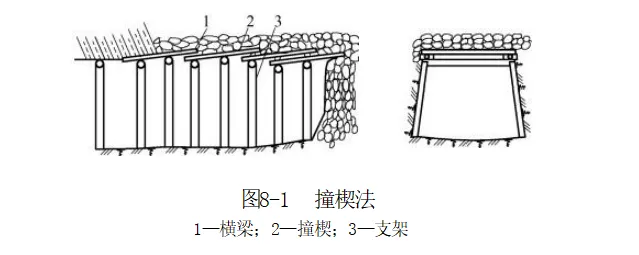
The wedge driving method, also known as the plate insertion method or sheet pile method, is a commonly used advanced support technique in the construction of tunnels in soft and fractured rock layers. When the tunnel excavation is about to reach the soft fractured rock layer, supports are first installed close to the working face. Then, wedges are driven from below the top beam of the rear support to above the top beam of the front support, starting from one corner of the roof. The wedges are generally made of hard wood, with a width of no less than 100mm, a thickness of 40-50mm, and a flattened pointed front end to reduce driving resistance. The length is usually 2 to 2.5 meters. When driving wedges, a wooden mallet is used to sequentially drive each wedge 100-200mm until the predetermined depth is reached, without exposing the roof. Under the protection of the wedges, mucking operations are carried out. When the mucking reaches two-thirds of the wedge penetration depth into the rock, mucking stops, supports are installed, and the second row of wedges is driven. This cycle continues until the fractured fault zone is passed.
During the excavation of the 850m level flat tunnel at Longyan Iron Mine, an extremely severe fault fracture zone was encountered with a large water inflow, initially reaching 150m³/h. Although two bypass tunnels were excavated successively, both collapsed and could not be passed, but they served to drain water, reducing the inflow to 10m³/h. Ultimately, the mine adopted a method of reducing the cross-section, fully supporting the walls and roof, and driving wedges above and below the beams, successfully controlling the flowing sand and smoothly passing through the difficult construction section. This example fully demonstrates the effectiveness of the wedge driving method in dealing with complex geological conditions, especially in controlling flowing sand and preventing tunnel collapse. The wedge driving method is an effective approach for passing through fault fracture zones, water-bearing flowing sand layers, and soft mud layers without special equipment, with relatively high construction safety. However, it has obvious limitations: slow construction speed, as each cycle of wedge driving, mucking, and support installation takes considerable time; high consumption of manpower and materials, as wedge driving requires manual operation and a large amount of wedge materials. Therefore, in practical applications, the method should be chosen after weighing the pros and cons based on specific project conditions.
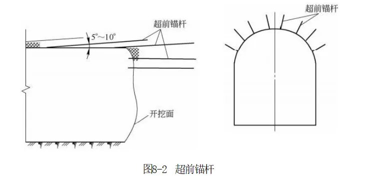
Advanced rock bolts are installed before excavation by drilling longitudinal holes along the contour line of the working face with a slightly larger outward inclination angle and installing bolts to pre-anchor the surrounding rock ahead. In practice, this is equivalent to the traditional plate insertion method and can effectively prevent surrounding rock collapse during excavation. Advanced rock bolts are drilled using rock drills, making construction convenient without requiring complex equipment or technology, and can be easily carried out in various mine tunnel constructions. However, they are relatively flexible with low overall stiffness, which limits their reinforcement effect and range. When facing large surrounding rock pressures, they cannot provide sufficient support. Therefore, advanced rock bolts are best used in conjunction with steel arches, leveraging the rigidity of steel arches to enhance overall support effectiveness. Regarding support parameters, advanced rock bolts are generally set longitudinally in the arch area and, if necessary, locally near the arch foot. The half-arc length range for setting advanced rock bolts in the arch area is l = (1/2 to 1/3) a, where a is the half-length of the outer arc of the rock tunnel arch. Depending on the surrounding rock conditions, double or triple layers can be used, with the front and rear support groups overlapping by no less than 1 meter in horizontal projection longitudinally. In terms of materials, advanced rock bolts should use early-strength cement mortar bolts or resin bolts, and composite hollow bolts can also be used. The strength grade of the cement mortar should not be lower than M20. The length should be 3 to 3.5 meters and greater than twice the advance length plus 1 meter of overlap. They are usually installed simultaneously with systematic bolts and used in conjunction with lattice arches, passing through the web of the lattice arch and welded to it.
In the construction of the electric locomotive chamber and substation at 635m level of Fushun Longfeng Mine, advanced rock bolts were successfully applied in fractured rock layers. The rock in this section was fragmented, making construction difficult and prone to roof collapse accidents if not handled carefully. Construction personnel first used 1.7m long steel wire rope cement mortar bolts (spaced 600mm apart) as advanced supports. Under this support, the fractured zone was safely passed. After passing, additional bolts were promptly installed and shotcrete applied to further enhance the stability of the surrounding rock. This case fully demonstrates the important role of advanced rock bolts in fractured rock layer construction, providing safety assurance for subsequent construction under complex geological conditions. However, due to their own stiffness and support effect limitations, in areas with higher surrounding rock pressure or more complex geological conditions, using advanced rock bolts alone may not meet support requirements and must be combined with other support methods.
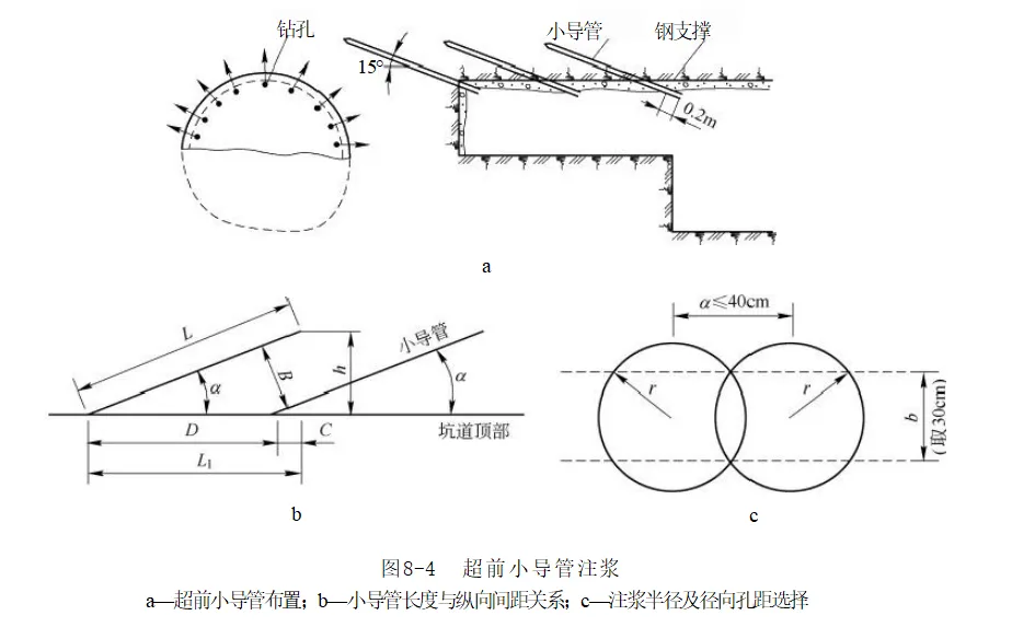
Advanced small pipe grouting involves spraying concrete to seal the excavation working face before tunnel excavation, then driving steel pipes with a diameter less than 50mm and perforated walls into the surrounding rock along the arch contour line at a certain outward inclination angle. Grouting is performed through the steel pipes to form a consolidation body in the tunnel arch area, thereby reinforcing the surrounding rock.
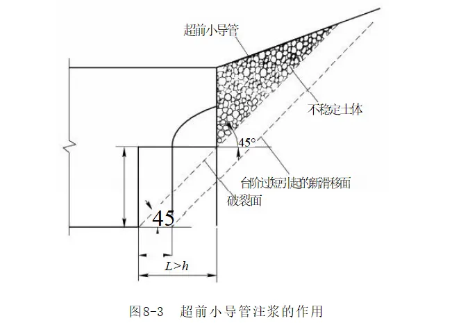
Advanced small conduit grouting has unique advantages, combining the advanced support of anchor bolts and the dual function of grouting reinforcement of the surrounding rock, effectively improving the structure of the working face surrounding rock. Under its effect, a reinforcement layer with a thickness of 0.5 - 1m can be formed on the roadway surface, which, together with the steel arch and surrounding rock, forms an advanced support structure that effectively stabilizes the surrounding rock and controls surface settlement in the tunnel portal section. Compared with advanced anchor bolts, the advanced small conduit is longer, with better support stiffness and pre-support effect; compared with pipe sheds, it is simpler, more flexible, economical, and requires simpler construction equipment. However, advanced small conduit grouting also has certain limitations: the construction period is relatively long, each grouting and small conduit installation operation takes considerable time, significantly affecting the excavation cycle; due to the low grouting pressure, the slurry diffusion range is small, generally only 0.4 - 0.5m, so the support capacity is inferior to pipe sheds. Regarding support parameters, the reinforcement length is 2 - 3 times the excavation advance length and not less than 0.4 times the tunnel span. The small conduit length is generally 3 - 6m, with a horizontal longitudinal overlap length of 0.5 - 1m between two groups of small conduits. The transverse reinforcement range of the arch crown is 120°, with long anchor bolts used at the lower part, and the outward insertion angle generally 10° - 15°, related to the length of the small conduit and the spacing of the steel arch. The circumferential spacing is determined according to the geological conditions ahead and the self-stability capacity, following the principle of superimposing the grouting range. The spacing of small conduits is 1.5 - 1.7 times the measured slurry diffusion radius, generally 300 - 500mm. Small conduits should be used in conjunction with grid arches; the exposed end of the small conduit tail is usually supported on the grid arch behind the working face and welded to it, jointly forming an advanced support system.
In a certain tunnel construction, the tunnel crosses a fault fracture zone where the surrounding rock is extremely fragmented and has very poor self-stability. Multiple signs of collapse appeared during construction. The construction team adopted advanced small conduit grouting support technology, drilling small conduits along the tunnel arch contour line and performing grouting. Through this measure, the surrounding rock was successfully reinforced, allowing the tunnel to pass smoothly through the fault fracture zone. After grouting, monitoring of the surrounding rock showed that deformation was effectively controlled, ensuring the safety of tunnel construction. This example fully demonstrates the effectiveness of advanced small conduit grouting in coping with complex geological conditions. It can quickly form an effective support structure under poor surrounding rock conditions, creating safe conditions for subsequent construction. However, in practical application, support parameters need to be reasonably determined according to specific geological conditions and engineering requirements to ensure the support effect.
Pipe shed support is a method used before rock roadway excavation, where steel pipes with a diameter greater than 70mm are drilled forward along the outer contour line of the excavation working face at certain intervals and small outward insertion angles. The tail of the steel pipes is welded to the steel arch frame, and cement slurry or mortar is injected into the surrounding rock through the steel pipes, forming an integrated advanced support system with the surrounding rock.
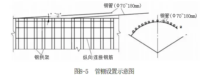
Pipe shed support has many significant features. In terms of support structure, it needs to be used in conjunction with steel arch frames. The steel pipes serve as longitudinal support, the steel arch frames as transverse support, and the steel arch frames also support the end of the pipe shed. After grouting, the pipe shed and surrounding rock together form a load-bearing arch with high stiffness and bearing capacity, effectively supporting the fractured surrounding rock above the rock roadway. Regarding grouting, the pipe shed uses filling extrusion grouting, where a slurry with higher consistency is injected through holes in the pipe wall into the surrounding rock to fill and extrude it, improving the integrity of the surrounding rock near the pipe shed and acting as a water-blocking curtain. When combined with initial support, the pipe shed can exert stronger support effects and can also serve as an independent reinforcement method for surrounding rock, used as permanent support. Pipe sheds are divided into short and long pipe sheds; steel pipes shorter than 15m are called short pipe sheds, and those longer than 15m are long pipe sheds. Short pipe sheds have a smaller one-time advanced support distance, with relatively easy drilling and pipe insertion, but frequently intersect with excavation operations, occupying more cycle time. Long pipe sheds have a larger one-time advanced support distance, fewer installations, less interference with excavation, and are suitable for large and medium-sized machinery in large-section excavation. Regarding support parameters, the pipe shed length should be determined based on geology, drilling equipment, and construction conditions, generally 10 - 40m. The front end of the pipe shed should exceed the length of weak and fractured surrounding rock plus the length of the working face relaxation caused by excavation. If a long pipe shed section is needed, it should be set in segments. To ensure sufficient advanced length after excavation, the horizontal overlap length of two longitudinal rows of pipe sheds should be greater than 3m. Since weak surrounding rock supported by pipe sheds is often excavated by the bench method, pipe sheds are generally arranged only at the arch of the rock roadway, with radial layout range determined by bench division, generally about 120°. The outward insertion angle of the pipe shed should consider the sag of the drilling tool, generally 1° - 5°, decreasing as pipe shed length increases. The circumferential spacing of pipe sheds should be determined according to geological conditions, construction length, and horizontal drilling curvature. The center distance of steel pipes should be 2 - 3 times the pipe diameter; considering collapse prevention and waterproofing, it is generally 300 - 500mm. In a certain metro tunnel construction, the section was in sandy gravel strata with very poor self-stability of surrounding rock, and important buildings above the tunnel required strict surface settlement control. The construction team used pipe shed support technology, drilling 30m long, 108mm diameter steel pipes along the tunnel arch contour and performing grouting reinforcement. Under the effect of pipe shed support, deformation of the surrounding rock and surface settlement were effectively controlled, ensuring tunnel construction safety and the safety of the buildings above. This case fully reflects the key role of pipe shed support in coping with complex geological conditions and strict settlement control requirements. However, pipe shed support also has some disadvantages: complex construction technology, high requirements for drilling accuracy, steel pipe installation accuracy, and grouting process; high precision requirements, where any deviation in any step may affect support effect; high cost, with steel pipes, steel arch frames, and grouting materials being expensive; slow construction speed, with drilling, steel pipe installation, and grouting being time-consuming. Therefore, in practical application, comprehensive consideration of geological conditions, construction requirements, and costs is needed to carefully decide whether to adopt pipe shed support.
Comprehensive Case Analysis Through the analysis of multiple mining engineering cases such as Longyan Iron Mine, Wugang Jinshandian Iron Mine, Fushun Longfeng Mine, Beizao Coal Mine, and Gansu Jinchuan No. 2 Mining Area, it can be seen that different construction methods each have their advantages and disadvantages in the construction of roadways in soft rock layers. The wedge driving method applied in Longyan Iron Mine successfully solved the problems of fault fracture zones and water inflow, but the construction speed was slow and it consumed a lot of manpower and material resources; the use of advanced anchor bolts in Fushun Longfeng Mine ensured the safety of construction in fractured rock layers, but its own support capacity was limited; advanced small-diameter pipe grouting effectively reinforced the surrounding rock in a certain tunnel construction, although the construction period was long; pipe shed support controlled surrounding rock deformation and surface settlement in a certain subway tunnel construction, but the construction technology was complex and costly. These cases indicate that in the construction of roadways in soft rock layers, the selection of appropriate construction methods should be comprehensively considered based on specific geological conditions, engineering requirements, and cost budgets. At the same time, different construction methods can also be combined to leverage their respective advantages to achieve better construction results. Future research can further explore the optimized combinations of various construction methods, as well as the application of new materials and new technologies, continuously improving the technical level and engineering quality of roadway construction in soft rock layers.
Summary The construction of roadways in soft rock layers faces many challenges, but the construction methods are rich and diverse, each with its own characteristics and applicable scope. The wedge driving method provides advanced support by driving wedges into soft fractured rock layers; it is safe but slow and consumes a lot of manpower and materials, suitable for crossing fault fracture zones and other complex geological conditions when special equipment is lacking; advanced anchor bolts are installed by drilling with rock drills, convenient for construction but with low stiffness and limited reinforcement range, mainly used in weak fractured sections with low surrounding rock stress and little groundwater; advanced small-diameter pipe grouting combines advanced support and grouting reinforcement, improving the surrounding rock structure with better support effect than advanced anchor bolts, but with a long construction period, suitable for weak surrounding rock with short self-stabilization time; pipe shed support combined with steel arch frames forms a load-bearing arch with high stiffness and bearing capacity, effectively controlling surrounding rock deformation and surface settlement, but the construction technology is complex and costly, suitable for shallow burial or surrounding rock with very poor self-stabilization ability. In actual projects, it is necessary to comprehensively consider geological conditions, engineering requirements, and cost budgets to accurately select appropriate construction methods. Geological conditions are fundamental; different rock characteristics, degrees of fracturing, and water content determine the feasibility and effectiveness of construction methods; engineering requirements include the purpose, size, and stability requirements of the roadway, which play a key guiding role in the selection of construction methods; cost budgets limit the application scope of construction methods, requiring the choice of economical and reasonable methods while ensuring engineering quality. Multiple construction methods can also be combined to complement each other and maximize advantages.