-
About Us
-
-
-
Contact Us

The Basic Concepts and Applicable Scenarios of the Inclined Shaft Development Method – Heijinggang Broadcast
The Basic Concepts and Applicable Scenarios of the Inclined Shaft Development Method
Definition of Technology and Its Core Features
The inclined shaft development method uses an inclined shaft as the primary access roadway, connecting the surface to underground ore bodies—a technique for mining deposit exploitation. Its core feature is the construction of three-dimensional transportation, ventilation, and personnel-access channels via inclined tunnels (with dip angles typically ranging from 10° to 45°). This method is particularly suited for gently inclined (dip angle 8°–30°) to steeply inclined (dip angle 30°–55°) ore bodies located beneath the ground surface, making it especially advantageous for the extraction of small- to medium-sized mineral deposits buried at depths of less than 200 meters. By combining various hoisting systems with tailored tunnel layouts, this approach ensures efficient ore transportation and streamlined mine development.
Geological Suitability Conditions and Engineering Advantages
Suitable for geological settings with relatively thin ore bodies (typically less than 15m thick), extensive strike lengths, and gently undulating floor structures. Its engineering advantages include: lower construction difficulty and shorter infrastructure timelines—reducing the project duration by 30% to 50%—as well as reduced initial investment (saving 20% to 30%) compared to shaft development. In contrast to adit development, it can access deeper buried ore bodies while offering greater flexibility in transportation systems. This method is typically applied to large-scale mining operations of both metallic minerals (such as lead-zinc and iron ores) and non-metallic minerals.
Classification of inclined shaft development: A technology system based on the hoisting method
Skip Hoisting Inclined Shaft (Inclination > 30°)
The skip hoisting inclined shaft is an efficient transportation method well-suited for mining operations in steeply inclined ore bodies. In this system, the skip serves as the core lifting container, capable of handling single-trip loads ranging from 5 to 30 tons, with lifting speeds reaching 4 to 8 meters per second—perfectly meeting the demand for rapid, large-scale ore transportation. Take the No. 6 skip-inclined shaft at Yiliang Chihong Maoping Mine as an example; serving as a critical passage for the Huoxi production succession project, this inclined shaft has significantly enhanced the speed of track bed construction through the adoption of "segmented, parallel construction" technology. This advancement not only paves the way for subsequent rail-laying activities but also facilitates the coordinated commissioning of the hoisting system and skips, while smoothly introducing the use of railcars. Ultimately, these measures ensure efficient transportation support for the development of mid-to-deep-level mineral resources.
However, the skip hoisting inclined shaft also has certain limitations: the equipment purchase and maintenance costs are relatively high, requiring a specialized technical team for regular inspections. Additionally, the construction of unloading chambers and ore storage bins further increases both the project's complexity and investment expenses.
String car hoisting inclined shaft (slope angle 25°~30°)
The skip hoisting inclined shaft uses a skip train—composed of multiple mine cars—as the transportation unit, making it suitable for moderately inclined ore bodies. This lifting method features relatively simple equipment and high flexibility, offering significant advantages in mines with complex terrain or variable ore-body conditions. A single-hook skip train can handle an annual capacity of approximately 10 to 300,000 tons, while a double-hook skip train can achieve up to 500,000 tons per year, effectively meeting the production needs of mines of varying scales. In a coal mine in Guizhou, designed with a production capacity of 90,000 t/a, the shaft was excavated along the coal seam dip at a 22° incline from the coal seam floor. At specific locations, transport crosscuts were driven to expose the coal seam, which were then connected via an inclined-shaft suspension bridge. This setup enables efficient operations such as coal transportation, gangue removal, material delivery, and pedestrian access, with material transfer underground facilitated by either a car-dumping yard or a flat-car yard.
However, the skip hoisting inclined shaft also suffers from transportation interruptions and relatively low efficiency, and it requires strict control over the reliability of skip connections to prevent runaway car accidents.
Belt Conveyor for Inclined Shaft (Slope <18°)
The inclined shaft conveyor system uses steel-cord-reinforced conveyor belts as the transport medium, enabling continuous ore transportation and ideally suited for gently inclined ore bodies. This method boasts a high conveying capacity—exceeding 1,000 tons per hour—and features advanced automation, significantly reducing labor requirements while boosting production efficiency. For instance, the main inclined shaft conveyor system at Datong Coal Mine is equipped with a KHP-119-type belt-break protection device that continuously monitors the belt's operational status. In the event of a belt break or slippage (over-speed), the system swiftly activates its gripping mechanism, simultaneously cutting off power to the conveyor control circuit and triggering both audible and visual alarms, thereby ensuring safe and reliable transportation operations.
The conveyor belt system used in the inclined shaft upgrade demands high shaft alignment precision, necessitating a comprehensive monitoring system equipped with features to prevent belt misalignment and tearing, thereby ensuring stable operation of the conveyor.
Comparison of Inclined Shaft Layout Plans
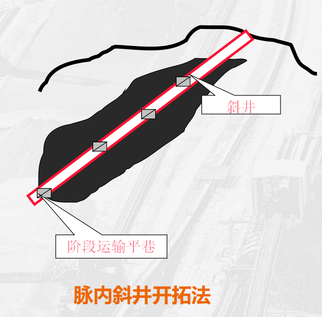
(1) In-pit inclined shaft development method: Directly connecting the orebody from within.
Layout Features and Engineering Structures
The intramural inclined shaft development method involves driving the inclined shaft directly into the ore body, close to its lower contact zone, and aligning it along the dip of the ore deposit. Connections between the inclined shaft and the stage-level transport drifts are established solely via the bottom-of-shaft car shed, eliminating the need for separate adits. Typically, 8–10 meters of safety pillars must be left on either side of the shaft to ensure its stability during mining operations. In a real-world case study at an iron mine, where the ore body was layered, relatively thin but extensively distributed, the intramural inclined shaft method was employed. During construction, the inclined shaft directly exposed the ore body, which not only facilitated efficient mining and ore transportation but also enabled simultaneous exploration as the ore body was uncovered. As a result, the overall construction period was reduced by 25% compared to conventional methods. Moreover, the excavation of the inclined shaft yielded a significant amount of secondary ore, generating additional economic benefits for the mine.
Advantages, Disadvantages, and Applicable Scenarios
From the perspective of advantages, the in-pit inclined shaft development method eliminates the need to excavate stone gates, significantly reducing infrastructure investment. Compared to the lower-side inclined shaft method, infrastructure costs can be cut by 15% to 20%. At the same time, the construction timeline is also shortened accordingly, enabling mines to reach production more quickly—with an increase in production start-up speed of approximately 30%. Moreover, since the inclined shaft is located inside the orebody, it also serves as a complementary tool for exploration, enhancing the understanding of the mineral deposit.
However, this method also has some drawbacks. Since the inclined shaft is located within the orebody, it is necessary to leave behind safety pillars, which are typically difficult to reclaim, resulting in resource losses of approximately 5% to 8%. Moreover, when the dip angle of the orebody's roof or floor fluctuates by more than 15°, maintaining the stability of the inclined shaft becomes challenging, negatively impacting its hoisting capacity and operational safety, while also increasing equipment wear and the risk of accidents.
Based on these advantages and disadvantages, the intravein inclined shaft development method is primarily suitable for ore bodies that are relatively thin in thickness, large in area, and exhibit minimal undulation in their floor. When the underlying rock strata are unstable, while the ore itself is stable yet of low economic value—such as in the extraction of non-metallic minerals like limestone or sandstone—it is particularly appropriate to adopt the intravein inclined shaft method. Additionally, for projects with insufficient ore deposit exploration but an urgent need for short-term production, this method can be effectively utilized to rapidly establish a mining system, allowing for further exploration of the ore body during the actual extraction process.
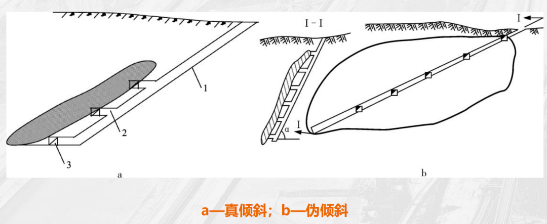
Downward Inclined Shaft Development Method: Stable Layout Within Surrounding Rock
The down-dip inclined shaft development method involves placing the inclined shaft within the surrounding rock beneath the orebody, typically maintaining a distance of more than 15 meters between the shaft and the orebody to minimize the impact of mining activities on the shaft itself. This method connects the orebody directly to the surface via various types of shaft bottom stations and crosscuts (with crosscut lengths usually ranging from 5 to 30 meters), which are linked to stage-level transport drifts. Depending on the relationship between the inclined shaft and the orebody’s strike and dip, the shaft can be laid out either at true inclination (where the shaft’s angle matches the orebody’s dip) or at pseudo-inclination (particularly suitable for steeply dipping orebodies, as it allows for a gentler shaft angle, facilitating hoisting operations). For instance, at the Maoping Lead-Zinc Mine, where certain orebodies are steeply inclined, the down-dip inclined shaft development method was adopted, with the shaft designed at a pseudo-inclination. Such rational planning effectively reduced hoisting challenges, ensured the long-term stability of the shaft during continuous mining, minimized failures in hoisting equipment, and ultimately boosted the mine’s overall production efficiency.
The lower-dip inclined shaft development method offers numerous advantages. Since the inclined shaft is situated in the stable surrounding rock beneath the orebody, there is no need to leave safety pillars, resulting in a resource recovery rate that is more than 10% higher compared to the vein-inclined-shaft method. Additionally, the shaft maintains excellent conditions for maintenance, reducing maintenance costs by approximately 20%, and remains unaffected by fluctuations in the orebody floor, ensuring the long-term stability and reliable operation of the inclined shaft.
However, its drawbacks are also quite evident: compared to the in-pit inclined shaft method, it increases the volume of stone gate construction, with each stage requiring stone gates approximately 20–50 meters long. As a result, capital investment rises by 10%–15%, and the overall infrastructure timeline is also extended accordingly.
This method is suitable for most gently dipping metal ore bodies and is the most widely used in metal mines, accounting for over 70% of applications. It is particularly well-suited for cases where the ore body is thick, covers a large area, and features significant variations in the underlying floor elevation. When the value of the ore is high and it’s crucial to ensure mining safety while minimizing resource losses, the lower-pit inclined shaft development method is an ideal choice.
Engineering Applications and Technical Key Points of Inclined Shaft Development
(1) Key Parameters for Shaft Design
Pitch Angle Optimization
Determining the dip angle of an inclined shaft is a complex and critical process that requires comprehensive consideration of hoisting equipment selection and the geological characteristics of the ore body. For belt conveyors, to ensure stable operation and smooth material transportation, the shaft inclination must be kept below 18°. In contrast, when using skip hoisting, the shaft inclination typically needs to exceed 30° to meet the loading and unloading requirements of the skips as well as optimize lifting efficiency. In practical engineering applications, establishing a three-dimensional model and simulating the dynamic behavior of the hoisting system allows for precise analysis of how equipment performs at various incline angles, enabling engineers to anticipate potential issues—such as skip oscillation or belt misalignment—and ultimately providing a scientific basis for optimizing the shaft angle. This approach ensures the safe and reliable operation of the entire hoisting system.
Section dimensions
The design of the inclined shaft's cross-sectional dimensions is based on the size of the transportation equipment and ventilation requirements. Taking a skip hoisting inclined shaft as an example, the cross-sectional width must be increased by a safety clearance of 1.2 meters beyond the skip's width to prevent collisions between the skip and the shaft wall during lifting. Meanwhile, the height must meet the needs for equipment installation, maintenance, and personnel passage. In terms of ventilation, according to the "Coal Mine Safety Regulations," the wind speed in inclined shafts generally should not exceed 8 m/s. The required ventilation cross-sectional area is determined by calculating the airflow volume, which in turn dictates the net cross-sectional area of the inclined shaft—typically ranging from 8 to 15 square meters—to ensure smooth underground ventilation and provide workers with a safe and comfortable working environment.
Support Structure
For the inclined shafts within stable ore bodies, anchor-spray + steel mesh support is employed. Anchors are used to firmly bond the surrounding rock with the stable rock mass, while sprayed concrete forms a protective layer. Meanwhile, the steel mesh enhances the tensile strength of the concrete, effectively improving the stability of the support structure. In contrast, for inclined shafts situated in fractured surrounding rock, concrete lining is required as the primary support system. Typically, the lining thickness ranges from 300 to 500 mm. This approach leverages the high strength and monolithic nature of concrete to resist the pressure exerted by the surrounding rock, ensuring the long-term safety and reliability of the inclined shaft.
(II) Technologies for Enhancing Safety and Efficiency
Intelligent Monitoring System
The intelligent monitoring system is a key technology that ensures the safe operation of inclined shafts. By using an electromagnetic induction-based detector to perform flaw detection on steel cables, the system can instantly identify internal damage such as wire breaks, wear, and corrosion, promptly uncovering potential safety hazards. Meanwhile, the hoist vibration monitoring system employs high-precision sensors capable of detecting vibrations as low as 0.01 mm/s. Through detailed analysis of these vibration signals, the system accurately assesses the hoist's operational status, predicts the likelihood of future failures, and enables proactive fault diagnosis. This not only provides critical insights for equipment maintenance and repairs but also guarantees the safe and reliable operation of the entire lifting system.
Rapid Construction Techniques
“The drill-and-blast method combined with mechanized support systems is an effective approach to enhancing the efficiency of inclined shaft construction. In the drilling and blasting phase, medium-to-deep hole blasting technology is employed, increasing the depth of blast holes to maximize the amount of rock broken per blast. Mechanized support includes the use of large-scale drilling rigs for drilling operations, loaders for rock-loading tasks, and haulage vehicles for muck removal, ensuring seamless coordination among all processes and enabling monthly advance rates of 80 to 120 meters. For instance, at the Maoping Mine, the No. 12 Metallurgical Construction Company successfully implemented a segmented parallel construction technique, dividing the inclined shaft project into multiple segments that operate simultaneously in parallel. This innovative approach significantly reduced the overall construction timeline, cutting the project duration by 15% compared to conventional methods.”
Anti-Runaway Car Device
In the string car hoisting system, the "one slope, three barriers" is an essential safety device, comprising a car stopper, a barrier rail, and a barrier gate—each strategically placed at the upper, middle, and lower sections of the inclined shaft. These components effectively prevent runaway accidents during the hoisting process. Paired with an overspeed protection device, this system can respond swiftly within 0.5 seconds by activating braking measures whenever the string car exceeds the preset speed, thereby averting potential accidents and ensuring safe operation of the inclined shaft hoisting system.